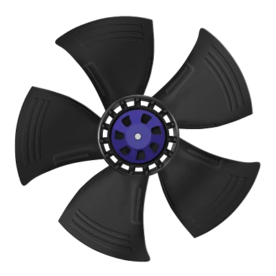
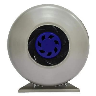
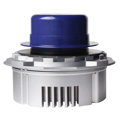


Suzhou Blauberg Motoren Technology Co., Ltd. is one of the leading manufacturers and suppliers of blauberg gc-b310c-ec-f05 310mm ec plug fan in China. Welcome to buy bulk high quality customized products made in China here and get quotation from our factory. For price consultation, contact us.
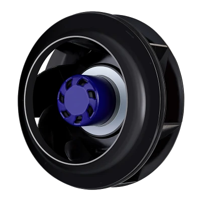
The Blauberg GC-B310C-EC-F05 is a 115 VAC EC backward-curved centrifugal plug fan with a support frame and an aluminum-alloy impeller. It operates at a nominal speed of 2500 RPM and supports 0-10 VDC or PWM speed control, tachometer feedback and RS485 Modbus RTU communication.
| Model | GC-B310C-EC-F05 | Product Type | EC Backward-Curved Centrifugal Plug Fan |
| Phase | 1~ | Data Method | FA (Free Air) |
| Nominal Voltage | 115 VAC | Nominal Voltage Range | 92-138 VAC |
| Frequency | 50/60 Hz | Nominal Speed | 2500 +/-5% RPM |
| Maximum Input Power | 380 W | Maximum Input Current | 3.4 A |
| Sound Level | 82 dB(A) | Ambient Temperature | -25 deg C to +60 deg C |
| Conformity | CCC, CE, RoHS | Motor Size | 102 |
| Dimensions | 440 x 440 x 207 mm | Impeller | Aluminum alloy, 6 blades |
| Air Flow Direction | All around | Rotation | Clockwise, viewed toward rotor |
| Degree of Protection | IP44 | Insulation Class | Class F |
| Duty / Bearing | S1 / Ball bearing | Installation | Any position |
| Speed Control | 0-10 VDC / PWM, maximum input 10 VDC | Voltage Output | 10 VDC, maximum 10 mA |
| Communication | RS485, Modbus RTU | Signal Feedback | Tachometer output, 5 pulses per revolution |
| Protection | Locked-rotor, thermal, overvoltage, undervoltage, overcurrent and soft-start protection | Power Factor Correction | PFC |
| Cable Length | 500 +/-20 mm | Operating Humidity | 5%-90% RH |
| Transport / Storage | -40 deg C to +80 deg C, 5%-95% RH | Cooling | Rotor-side cooling openings |
| 1 | Charging Column | 9 | Equipment Cooling Project |
| 2 | Kitchen Smoke Exhaust System | 10 | Ventilation Unit Project |
| 3 | FFU Project | 11 | AHU Project |
| 4 | Computer Room Cooling | 12 | Air Purifier Project |
| 5 | Rail Transit Air-Conditioning | 13 | Heat Exchanger Project |
| 6 | Electrical Appliances | 14 | Telecom Container Project |
| 7 | FanGrid Project | 15 | Data Center Cooling Project |
| 8 | Ventilation Equipment Project | 16 | Industrial Cooling System |
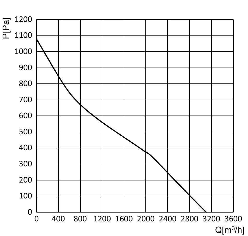
Air performance was measured according to AMCA210/GB1236 installation category A. The curve covers approximately 0-3600 m3/h and 0-1200 Pa. Values apply under the specified measuring conditions and may vary with installation conditions.

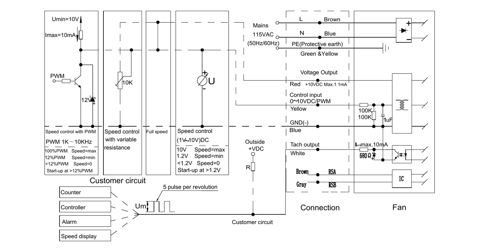
| Line | Connection | Designation | Colour | Function / Assignment |
|---|---|---|---|---|
| Power | PE | PE | Green / Yellow | Protective earth |
| Power | U1 | L | Brown | Power supply, live wire |
| Power | U2 | N | Blue | Power supply, neutral wire |
| Control | U3 | RSA | Brown | RS485 Modbus interface, RSA |
| Control | U4 | RSB | Gray | RS485 Modbus interface, RSB |
| Control | U5 | Speed Control | Yellow | 0-10 VDC / PWM control input, maximum PWM amplitude 10 V |
| Control | U6 | Signal Feedback | White | Tachometer output, 5 pulses per revolution |
| Control | U7 | +10 V | Red | Fixed 10 VDC output, maximum 10 mA |
| Control | U8 | GND | Blue | Reference ground for control interface |
The speed output uses a customer-provided pull-up resistor. Vfg = 3.3-30 VDC and R must be at least 1000 x Vfg ohms. Speed calculation: n = 60f / a, where n is fan speed, a is pulses per revolution and f is the signal-output waveform frequency.
Additional Notes
Connect the fan power and control lines strictly according to the wiring diagram to prevent damage.
Do not connect the white signal wire directly to the red signal wire or to an external DC power supply.
If the fan does not start, check the speed-control input voltage and wiring. Do not touch the impeller or rotor after power is applied.
The fan takes several seconds to start. Do not touch the impeller or rotor while energized or operating at low speed.
Before powering on, make sure the motor is installed securely.
Do not pull the power cable. If it is damaged, it must be replaced by the manufacturer.
Do not drop or strike the motor.
Do not flush the motor; reduced insulation performance can cause leakage and personal injury.
For applications outside the agreed operating conditions, consult Blauberg first.
The motor housing can remain hot after operation. Prevent direct contact and protect against burns.
During installation, keep the housing clear of debris and clean the interior if necessary.
Before installation and operation, turn the rotor by hand to confirm there is no collision, interference or jamming.
The motor is part of the fan and must not operate without an impeller or load.
After unpacking, repackage the product for storage. Store it in a clean, ventilated warehouse at -40 deg C to +80 deg C, relative humidity not more than 95%, without corrosive gases, and at least 15 cm above the floor.
Install the fan out of reach of children and do not allow children to use it.
The final interpretation of this specification belongs to Blauberg.
Life and Maintenance, Warranty
The design life is 50,000 hours, limited by the ball-bearing life of 50,000 hours at 40 deg C. Actual service life varies with temperature, humidity, installation, load and operating environment.
Depending on the environment, clean and maintain the fan every 3-6 months.
The complete fan has a two-year warranty from the purchase date, subject to the delivery date of the order. Failures caused by product quality are eligible for repair or replacement; damage caused by improper disassembly, handling, human action, natural disaster or force majeure is not covered.
GC-B310C-EC-F05-Technical-Specification.pdf
Hot Tags: blauberg gc-b310c-ec-f05 310mm ec plug fan, China blauberg gc-b310c-ec-f05 310mm ec plug fan manufacturers, suppliers, factory