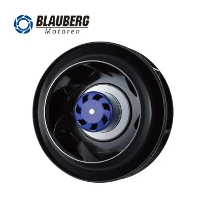

PTFE-Coated Centrifugal Fans for
35% Hydrogen Peroxide and VHP Equipment
A corrosion-risk selection framework for impellers, EC controls, operating points, and equipment-level validation
Executive Summary
Selecting a fan for ordinary HVAC equipment usually starts with airflow, static pressure, acoustic output, input power, and installation geometry. In equipment exposed to 35% hydrogen peroxide (H₂O₂) or vapor-phase hydrogen peroxide (VPHP), that sequence is incomplete. A fan may deliver the required air volume on day one while its impeller material, coating system, fasteners, interfaces, or balance condition gradually deteriorate under repeated chemical exposure. For pharmaceutical and biotechnology equipment manufacturers, the correct question is therefore not simply whether a centrifugal fan can move air. The question is whether a complete corrosion-resistant centrifugal fan solution can maintain structural integrity, controllability, and an acceptable working point throughout a defined chemical cycle.
In August 2025, a pharmaceutical-equipment company asked Blauberg whether an existing PA6+GF impeller could resist a 35% H₂O₂ environment and whether a polymer or alternative hydrogen peroxide resistant fan could be supplied for VPHP equipment. The enquiry became a joint engineering selection exercise covering chemical compatibility, impeller diameter, pressure capability, mounting space, low-voltage power, speed control, and the test method required to demonstrate suitability.
Blauberg developed two candidate routes: an electrophoretically treated galvanized-steel impeller for cost-sensitive or early structural trials, and a galvanized-steel impeller with PTFE surface treatment for the more demanding target environment. After comparing the routes, the customer purchased one BE-B190L-EC-03 and one BE-B250L-EC-N07 sample. Both use a 48 VDC EC platform and support 0-10 VDC or PWM speed control. The samples cover two installation envelopes and two airflow ranges while keeping the control architecture substantially consistent.
The project has entered equipment-level testing; it has not yet produced a universal chemical-compatibility certificate or a long-duration service-life claim. A PTFE-coated impeller is a risk-reduction design choice, not automatic proof of indefinite resistance. Final acceptance must be based on the real medium, concentration, temperature, exposure duration, number of cycles, condensation behavior, cleaning sequence, system resistance, and measurable post-cycle changes in coating condition, airflow, pressure, current, vibration, and noise.
Why Hydrogen Peroxide Changes Centrifugal Fan Selection
Hydrogen peroxide is widely associated with low-temperature decontamination and sterilization processes. In VHP or VPHP equipment, the air-moving system may recirculate, distribute, or remove a chemically active vapor inside an enclosure or treatment path. This creates a different duty profile from a conventional industrial ventilation fan. Fan surfaces can encounter repeated oxidizing exposure, variable humidity, temperature transitions, condensate, aeration phases, and residues at joints or edges. Material compatibility becomes a system question rather than a single-resin lookup.
Public guidance on hydrogen-peroxide sterilization repeatedly emphasizes material compatibility, and published evaluations show that hydrogen-peroxide exposure can affect some plastics, metals, plated parts, and coated goods. That does not mean every material will fail, nor does it mean one favorable compatibility chart is enough. Fan behavior depends on the finished component: substrate, surface preparation, coating thickness and coverage, curing, edge condition, attachment method, geometry, rotating stress, cleaning process, and exposure regime all matter.
For an OEM designing VHP sterilization equipment, a chemically affected impeller can create several secondary failures. Surface degradation or coating loss can change roughness and aerodynamics. Edge attack or deposits can alter mass distribution and dynamic balance. Increased vibration can load bearings and structures. A change in blade condition may reduce airflow at the required static pressure, increase noise, or move the operating point toward an unstable region. The resulting issue is not only replacement cost; it can affect circulation uniformity, pressure control, process repeatability, and equipment availability.
Case Requirements: Four Gates the Solution Had to Pass
The customer serves pharmaceutical and biotechnology applications as well as medical, radiation-safety, and custom-engineering projects. For the H₂O₂-related equipment platform, the fan had to satisfy four simultaneous gates: resist the intended environment, fit the available installation space, deliver useful airflow against system resistance, and integrate with the equipment power and control architecture. Passing only one or two gates would not produce a viable pharmaceutical ventilation system component.
|
Application requirement |
Project target |
|
Process medium |
35% H₂O₂ solution; application also involves VPHP |
|
Impeller size range |
190-250 mm |
|
Target airflow |
Approximately 300-1,500 m3/h |
|
Target pressure |
Approximately 500-600 Pa |
|
Power requirement |
Below 72 V |
|
Selection priorities |
Chemical compatibility, installed working point, geometry, controllability, and validation |
-
Chemical compatibility could not be inferred from a material name
The customer initially asked whether PA6+GF would resist the target environment. A material designation alone cannot support a defensible long-term answer because exposure concentration, vapor or liquid state, temperature, dwell time, number of cycles, mechanical stress, and cleaning practice change the result. The engineering team therefore reframed "corrosion resistance" as a set of observable acceptance criteria: surface discoloration, blistering, peeling, edge attack, changes at attachment points, loss of balance, and shifts in airflow, static pressure, current, vibration, or sound.
-
One equipment platform required two physical sizes
The requested 190-250 mm range represented more than a single drop-in replacement. Compact locations favored a 190 mm unit, while positions with more space or greater airflow demand favored a 250 mm unit. Selecting two samples allowed the customer to test both installation cases without forcing one fan to cover every operating condition. It also provided a controlled way to compare size and system-resistance effects while retaining the same PTFE treatment logic.
-
High-resistance operation required more than a maximum-airflow comparison
The target pressure of roughly 500-600 Pa shows that the equipment is not a free-air application. Filters, treatment chambers, transitions, bends, dampers, internal circulation paths, and discharge restrictions all contribute to the system curve. For a backward-curved centrifugal fan, the meaningful selection point is the intersection of the fan curve and the installed system curve at the intended control signal. Free-air volume and shut-off pressure are useful endpoints, but neither is the operating point.
Two Engineering Routes: Electrophoretic Treatment or PTFE
Blauberg proposed two routes so the customer could balance chemical risk, budget, and development stage. This approach is more useful than presenting one "best" material without context. Early mechanical integration, airflow testing, and aggressive chemical validation may justify different sample investments.
|
Route |
Models |
Impeller concept |
Best-fit decision context |
|
Route A |
BE-B190K-EC-03 / BE-B250K-EC-N07 |
Electrophoretically treated galvanized-steel impeller |
Lower initial cost; suitable for early structural checks, budget-sensitive trials, or environments whose corrosion intensity is demonstrated to be controlled |
|
Route B |
BE-B190L-EC-03 / BE-B250L-EC-N07 |
Galvanized-steel impeller with PTFE surface treatment |
Closer fit to the 35% H₂O₂ / VPHP risk profile; selected for equipment-level testing |
The lower-cost route was not dismissed as technically irrelevant. It could still support dimensional checks, mounting development, preliminary airflow measurements, or service conditions with less severe and properly verified exposure. However, the customer prioritized reducing the potential failure risk in its target chemical environment rather than minimizing sample price. It therefore ordered the two PTFE-treated versions.
Engineering Logic of a PTFE-Treated Metal Impeller
The selected concept combines a metal impeller substrate with PTFE surface treatment. The metal base provides the structural framework needed for a rotating component, while the surface treatment is intended to improve the impeller's suitability for the target chemical environment. In search terminology, buyers may look for a chemical-resistant blower, PTFE centrifugal fan, or corrosion-resistant EC fan. The engineering decision, however, must remain specific to the completed part and operating cycle.
A PTFE-coated centrifugal fan impeller for VHP equipment can offer a practical route when an OEM needs the geometry and stiffness of a metal wheel but wants an additional chemical barrier at exposed surfaces. The expected benefit depends on surface preparation, adhesion, continuity, cure quality, and coverage at blade edges, holes, joints, and other geometric transitions. A visually intact flat coupon cannot fully represent a rotating impeller with formed blades and connection details.
PTFE treatment must also be evaluated as part of the aerodynamic component. The coating cannot be permitted to interfere with critical clearances, create unacceptable surface defects, or introduce imbalance. Incoming inspection should therefore include visual condition, dimensional checks, runout or balance evidence where applicable, and baseline vibration and current data. These measurements make later cycle comparisons meaningful.
Important distinction. IP55 or IP44 describes enclosure protection under the applicable product definition; it does not certify resistance to 35% hydrogen peroxide or VPHP. Likewise, a general PTFE compatibility statement does not replace testing of the finished fan in the customer's process.
Selected Samples and Quantified Performance
The customer selected BE-B190L-EC-03 and BE-B250L-EC-N07, one sample of each. Both are DC backward-curved centrifugal fans built around a 48 VDC EC control platform. The pairing supports a practical low-voltage centrifugal fan architecture below the customer's 72 V limit while covering two space and airflow requirements.
|
Parameter |
BE-B190L-EC-03 |
BE-B250L-EC-N07 |
|
Overall / impeller size |
190 x 190 x 101.8 mm |
250 x 250 x 99 mm |
|
Rated voltage |
48 VDC |
48 VDC |
|
Voltage range |
38-57 VDC |
38-58 VDC |
|
Rated speed |
3,800 +/-5% rpm |
2,670 +/-5% rpm |
|
Maximum input power |
170 W |
200 W |
|
Maximum input current |
3.6 A |
4.3 A |
|
Nominal sound level |
76 dB(A) |
72 dB(A) |
|
Blade count |
7 |
11 |
|
Ingress-protection rating |
IP55 |
IP44 |
|
Impeller treatment |
Galvanized steel + PTFE |
Galvanized steel + PTFE |
|
Ambient temperature |
-25 to +60 C |
-25 to +60 C |
Approximate readings from the supplied P-Q curves indicate about 900 m³/h free-air volume and about 850 Pa shut-off pressure for the 190 mm sample. The 250 mm sample indicates about 1,900 m³/h free-air volume and about 960 Pa shut-off pressure. These are curve endpoints read approximately from the specification material, not guaranteed installed values. In the equipment, inlet and outlet geometry, clearance, flow distortion, temperature, density, and system resistance will change airflow, pressure, power, and noise.
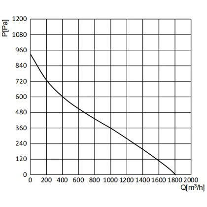
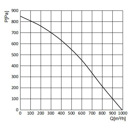
Approximate P-Q curves from the supplied specifications: BE-B190L-EC-03 (left) and BE-B250L-EC-N07 (right).
Selecting the Installed Working Point
The curve comparison is central to answering the long-tail query how to select a corrosion-resistant fan for pharmaceutical equipment. Chemical compatibility and airflow cannot be separated. A chemically robust impeller that operates far from the required pressure-volume point is not an acceptable solution, and an efficient fan that degrades during the chemical cycle is not acceptable either.
For the customer's approximate 500-600 Pa requirement, the engineering team should overlay or measure the equipment system curve and identify the expected working point for each speed command. The test should be performed with representative filters, chambers, ducts, dampers, and discharge conditions. If multiple process phases use different resistance states, the fan should be evaluated across all of them, including the most restrictive path and the aeration or purge mode.
The operating point should also be examined after repeated exposure. If the same command signal produces lower airflow or higher current after chemical cycling, engineers should determine whether the cause is coating change, deposits, altered clearance, bearing condition, system contamination, sensor drift, or another factor. Trend data is more informative than a single pass/fail reading.
One 48 VDC EC Control Platform for Two Sizes
Both selected samples operate from a nominal 48 VDC supply, with specified ranges of 38-57 VDC and 38-58 VDC. They support 0-10 VDC or PWM speed commands. This allows the customer to use a common low-voltage architecture and reduce duplicate integration work across the two installation positions. For buyers searching for a 48 VDC EC fan with 0-10V or PWM speed control, the case illustrates why electrical commonality can be as valuable as mechanical fit.
The EC platform also incorporates protective functions identified in the case material, including locked-rotor, overtemperature, overvoltage, undervoltage, overcurrent, and soft-start protection. These features support equipment integration and fault management, but they should not be described as process validation. The OEM must still confirm startup throughout the specified voltage range, command scaling, PWM frequency requirements, speed-feedback behavior, alarm logic, grounding, connector performance, and recovery after a simulated fault.
Control validation should include every process state: standby, ramp-up, treatment circulation, pressure regulation, purge, and shutdown. If the equipment uses closed-loop control, sensor placement and response should be assessed with both fan sizes. The objective is stable process control, not merely proof that the motor rotates.
Recommended Validation Protocol
The remaining step from "selection appears feasible" to "long-term reliable in this equipment" is structured validation. The following protocol is intentionally equipment-centered. It should be adapted to the customer's quality system, risk analysis, regulatory obligations, sterilant supplier instructions, and acceptance criteria.
1. Define the exposure cycle before testing
Record whether the fan encounters liquid spray, aerosol, vapor, condensate, or residual film. Specify H₂O₂ concentration, vapor concentration if measured, temperature, humidity, dwell time, injection phase, recirculation period, aeration period, shutdown time, number of cycles, and cleaning method. A statement such as "tested with peroxide" is not reproducible and cannot support material decisions.
2. Establish an incoming baseline
Before chemical exposure, photograph the complete impeller and high-risk details such as blade edges, holes, joints, hubs, and fasteners. Record mass if relevant, visual coating condition, dimensional clearance, fan speed, command signal, airflow, static pressure, input voltage, current, vibration, and sound under a controlled configuration. Retain the same instrumentation and fixture for repeat measurements.
3. Run corrosion cycles with staged inspections
Inspect after predefined cycle intervals rather than waiting for the final cycle. Look for discoloration, loss of gloss, softening, blistering, cracks, peeling, exposed substrate, corrosion products, deposits, edge damage, and changes at connection points. A hydrogen peroxide resistant centrifugal fan should be judged by both physical condition and functional trend, not appearance alone.
4. Measure airflow and static pressure in the assembled equipment
Record command input, rpm, airflow, static pressure, voltage, and current at representative operating points. Do not substitute free-air data for installed airflow. Verify that the working point remains inside a stable and controllable region and that the equipment achieves the intended circulation and pressure behavior across filter loading or other expected resistance changes.
5. Repeat vibration and acoustic measurements
Rising vibration or noise can reveal imbalance, deposits, coating loss, bearing stress, resonance, or operation away from the preferred region. If a trend is observed, inspect the impeller and system together. Chemical exposure may be one factor, but installation stiffness, inlet disturbance, accumulated residue, and control hunting can produce similar symptoms.
6. Confirm electrical and protection behavior
Verify start and continuous operation through the applicable 38-57/58 VDC range, 0-10 VDC and/or PWM control, speed feedback, current consumption, soft start, and each required protection response. Check connectors and wiring for compatibility with the actual environment, because an impeller-focused test can overlook vulnerable electrical interfaces.
Acceptance principle. Define pass/fail limits before testing. A robust plan states allowable coating change, maximum vibration growth, acceptable current deviation, minimum airflow and pressure retention, and any conditions that trigger teardown or redesign.
Commercial and Lifecycle Implications
The PTFE-treated samples cost more than the electrophoretically treated alternatives, yet the customer chose them because potential chemical failure carried a greater project risk than the incremental sample price. This is a common decision pattern in pharmaceutical, biotechnology, cleanroom, isolator, and decontamination equipment. The least expensive fan is not necessarily the lowest-cost option when premature replacement, engineering rework, field service, production interruption, validation delay, or inconsistent process performance are considered.
A lifecycle comparison should include acquisition cost, qualification effort, expected replacement interval, access time, contamination-control procedures, downtime, spare inventory, and the consequence of a failed process cycle. The current case does not yet provide enough long-term data to calculate return on investment or service life. Those claims should be made only after repeatable cycle and field data are available.
For B2B procurement teams, this supports a more precise search intent than a generic "fan supplier" query. Relevant high-intent phrases include centrifugal fan for VHP sterilization equipment, PTFE-coated impeller supplier, EC fan for pharmaceutical equipment, and chemical-resistant centrifugal blower manufacturer. These phrases connect the buyer's application risk with the engineering capability required to solve it.
Procurement Checklist for H₂O₂ and VPHP Fan Projects
Step 1 - Define the medium and cycle
State concentration, vapor or liquid form, temperature, humidity, condensation, exposure time, aeration, cleaning agents, and expected lifetime cycles. Include worst-case and normal conditions.
Step 2 - Define the installed duty point
Provide the required airflow and static pressure together, not as isolated maximum values. Share the system curve or enough equipment detail to estimate it, including filters, bends, chambers, restrictions, and changing resistance states.
Step 3 - Define the mechanical envelope
Specify impeller diameter, overall dimensions, mounting orientation, inlet and outlet clearances, access for service, and any balance or vibration limits. Confirm whether one equipment platform needs several fan sizes.
Step 4 - Define the electrical interface
Specify voltage range, maximum power availability, 0-10 VDC or PWM control, feedback, alarms, connector requirements, grounding, and protection behavior. Confirm these details against the formal product specification.
Step 5 - Compare material routes and validation cost
Evaluate substrate and surface treatment together. Compare lower-cost development samples with higher-resistance candidates, but include the cost of repeat testing, delayed qualification, and redesign. Request finished-component evidence rather than relying only on generic material charts.
Step 6 - Agree on acceptance criteria
Document visual, dimensional, aerodynamic, electrical, vibration, and acoustic limits before the first cycle. Establish inspection intervals and a root-cause process for any deviation.
Frequently Asked Questions
Can a PA6+GF impeller be used with 35% hydrogen peroxide?
It cannot be accepted or rejected responsibly from the designation alone. Suitability depends on the exact PA6+GF grade, additives, processing, stress, temperature, liquid or vapor exposure, duration, number of cycles, and finished-component geometry. The OEM should test representative parts under the actual cycle and monitor both physical and performance changes.
Is PTFE automatically resistant to every VHP process?
No universal equipment-level conclusion should be made from the polymer name alone. PTFE is selected in this case as a surface-treatment route intended to improve suitability, but performance depends on the completed coating system, coverage, adhesion, edge condition, substrate, mechanical stress, and exposure cycle. Equipment-level validation remains necessary.
What is the best centrifugal fan for 35% hydrogen peroxide environments?
The best centrifugal fan for 35% hydrogen peroxide environments is the one that passes both chemical and functional validation at the required installed working point. Key inputs include finished-component compatibility, airflow at static pressure, geometry, voltage, speed control, vibration, cleaning method, and lifecycle cycles. A product chosen only from maximum airflow or generic compatibility data is not fully qualified.
Why use a backward-curved EC centrifugal fan?
A backward-curved EC centrifugal fan can combine useful pressure capability with variable-speed control and a compact external-rotor architecture. In this case, the 48 VDC platform and 0-10 VDC/PWM control simplify integration across two sizes. Final efficiency, noise, and stability still depend on the installed working point and equipment geometry.
Do IP55 and IP44 prove peroxide resistance?
No. IP ratings and chemical compatibility address different questions. The IP rating should not be presented as evidence that the impeller, coating, connectors, or complete fan will withstand 35% H₂O₂ or VPHP exposure.
How should centrifugal fan material compatibility with vaporized hydrogen peroxide be verified?
For centrifugal fan material compatibility with vaporized hydrogen peroxide, define the exact cycle, inspect the finished part, establish aerodynamic and vibration baselines, conduct staged exposures, and repeat installed performance measurements. Acceptance should cover coating condition, balance, airflow, pressure, current, vibration, noise, and electrical interfaces.
Conclusion
This case demonstrates why fan selection for pharmaceutical and biotechnology equipment must go beyond "same size" and "similar airflow." Once 35% H₂O₂ or VPHP enters the duty cycle, the impeller substrate, surface treatment, geometry, control platform, installed system curve, and validation method collectively determine whether the solution is credible.
Blauberg converted the customer's original material question into two comparable engineering routes. The customer then selected one 190 mm and one 250 mm PTFE-treated sample, both on a 48 VDC EC platform, to cover different installation and airflow needs. The decision reflects a risk-based preference for a PTFE-coated impeller over a lower-cost electrophoretic option at the validation stage.
The next milestone is not a marketing claim; it is data. By recording chemical cycles, surface condition, installed airflow, static pressure, current, vibration, noise, and control behavior, the customer can determine whether the selected corrosion-resistant centrifugal fan solution progresses from technically plausible to demonstrably reliable in the real equipment.