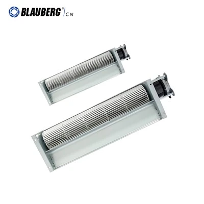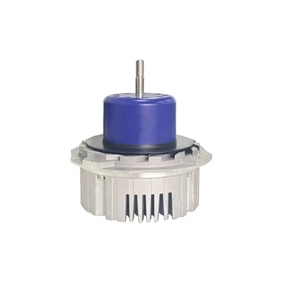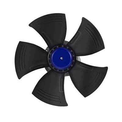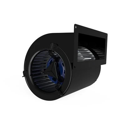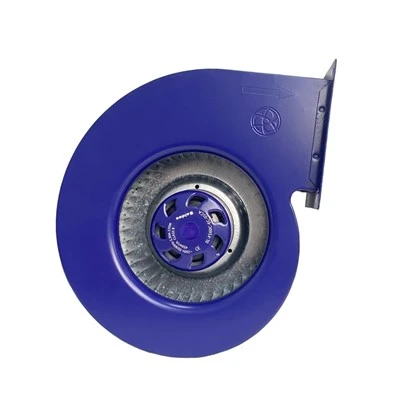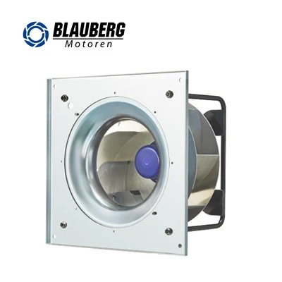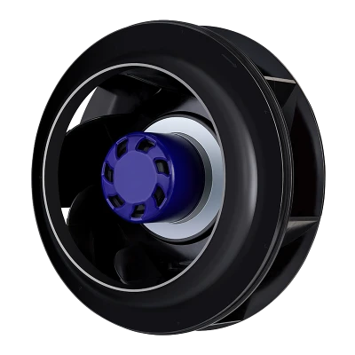
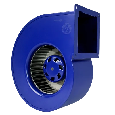
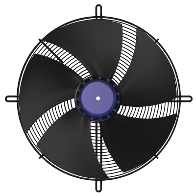
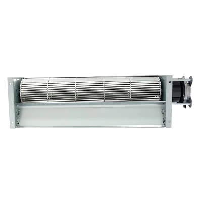
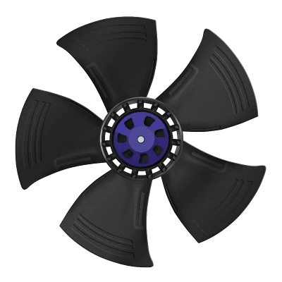
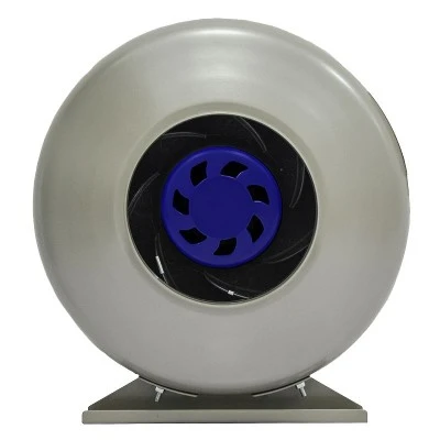
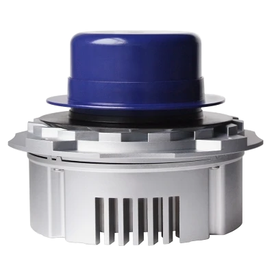
For wide, linear airflow, relatively low resistance and sufficient available length, consider a cross flow solution first. Where filters and ducts create higher resistance and concentrated airflow is needed, consider a centrifugal solution first. Thickness is only one constraint: verify the final choice against the same airflow duty under real installation conditions.
1. Define the airflow duty before choosing a fan that fits
Fan selection for slim equipment should not be based on installation thickness alone. Define the target airflow, pressure requirement, outlet width, air velocity in critical areas, input power and noise target. For heat-transfer equipment, determine airflow needs from the thermal load and allowable temperature difference. For systems with filters, also consider how resistance changes during use.
Cross flow fans, also known as tangential fans, use a long cylindrical impeller. Together with the housing and guide structures, it can produce a broad air stream distributed along the impeller length, making it suitable for elongated outlets. Actual airflow uniformity still depends on the impeller design, housing, grille and installation conditions. Centrifugal fans can also deliver broad airflow through ducts, but space requirements and additional pressure losses must be assessed for the specific configuration.
This article addresses concept selection rather than an overall ranking of the two fan types. Without specified models and measured performance curves, no universal minimum thickness, maximum static pressure or noise reduction can be stated.
2. Compare the complete installation envelope, not just impeller diameter
Space constraints in slim equipment usually involve thickness, length and width. Cross flow fans can use a longer impeller to provide broad airflow, but the housing, motor and inlet and outlet spaces must still be included. For centrifugal fans, check the axial inlet space, the scroll housing or discharge area for scroll-free designs, and the necessary duct connections. Impeller dimensions alone cannot establish whether a fan fits into the equipment.
Include the motor, brackets, guards, cable-bend space, inlet passage, outlet transition and maintenance removal direction in the three-dimensional installation envelope. Review these dimensions against the supplier's installation requirements rather than assuming a fixed inlet-clearance multiplier. For cross flow fans, also check the impeller-to-housing clearance, guide structures, and inlet and outlet openings. Do not reserve space solely around the impeller outline.
Check whether the slim enclosure obstructs the fan inlet or places the outlet too close to a wall. AMCA notes that actual inlet and outlet arrangements can introduce system effects, causing performance to differ from catalogue data. A smaller fan outline therefore does not necessarily make it easier to meet the equipment's airflow requirements.
3. A decision tree combining airflow pattern and system resistance
The first branch concerns the delivery pattern. If airflow is needed along an elongated area and sufficient length is available, prioritise a cross flow prototype. If air is mainly directed towards a local heat source, a duct or a concentrated outlet, first assess a centrifugal solution and its distribution arrangement.
The second branch concerns system resistance. Cross flow fans are generally better suited to applications with relatively low system resistance, but there is no pressure limit that applies to every model. For higher resistance, consider centrifugal fans first and confirm the operating point using the specific model's pressure–airflow (P–Q) curve. Pressure capability cannot be determined from fan type alone.
The third branch concerns the actual operating point. At the target airflow, can the candidate fan meet system resistance, input-power and stable-operation requirements? The fan performance curve and system resistance curve must use consistent pressure definitions, air density and comparable installation boundaries, accounting for system effects from the real installation. Free-air flow and maximum static pressure cannot simply be combined into an actual operating point.

| Decision point | Recommended action |
| Wide, linear airflow and sufficient length? | Yes: prioritise a cross flow solution. No: assess centrifugal fans or other feasible layouts within the installation space. Confirm the choice using performance curves and complete-equipment testing. |
| Can resistance be met at the target airflow? | Check fan performance and system resistance at the target airflow. Where filters are fitted, assess both clean and loaded conditions. If requirements are not met, change the model or airflow path. |
| Is the complete installation envelope feasible? | Check the motor, inlet, outlet, structure and maintenance access. Revise the equipment design if space is insufficient. |
| Does the complete equipment pass testing at the same duty? | Select after comparing airflow distribution, power consumption and acoustics on an equivalent basis. If verification fails, revise the design. |
4. Airflow uniformity requires more than total airflow
Two solutions delivering the same total airflow can have different distributions: one may be strong at the outlet centre and weak at the ends, while another is more even. If distribution across a heat exchanger, display or elongated workpiece matters, first specify the measurement plane, locations and evaluation metrics.
Use fixed measurement planes and locations, recording local velocities, the average and areas with insufficient airflow. Include edges and critical areas. The project parties should agree whether to use maximum deviation or another statistical metric. Do not state that uniformity must meet a particular percentage without supporting criteria.
If the prototype's distribution is inadequate, compare changes to grilles, flow guides or plenums. Recheck pressure loss, airflow and power consumption after every modification. Components that improve uniformity can also add resistance; assess the overall equipment benefit.

5. Compare noise at the same airflow duty
Do not rank the sound pressure of a cross flow prototype at a low-airflow setting against the sound power of a centrifugal prototype at its rated setting. First meet the same complete-equipment airflow duty, then align the test object, weighting, measurement distance, direction, background noise and installation conditions. Sound power level (Lw) and sound pressure level (Lp) are different quantities; their numerical difference cannot establish noise reduction.
Beyond the overall level, inspect the spectrum and prominent tones at commonly used settings, and check for installation resonance. Blade geometry is not a low-noise guarantee. Inlet obstruction, grilles, controls and structure-borne sound must all be included in equipment-level verification.
For a larger fan running at a lower speed, also check size, input power, low-speed control and cost. Comparisons must meet the same airflow and pressure requirements. Quietness achieved by delivering less air is not a selection advantage.
6. Complete final selection through prototype testing
Assess both fan concepts within the same equipment-envelope constraints and airflow duty. Allow each to use suitable inlet and outlet arrangements, recording space requirements and pressure losses. Use comparable test methods to record airflow, pressure, velocity distribution, input power, speed, noise and maintenance access. If filter loading or multiple operating settings are relevant, verify representative conditions as well.
During design review, distinguish between 'Meets requirements', 'Modification needed' and 'Insufficient evidence'. The best solution for slim equipment is not the thinnest or quietest fan in a catalogue. It is the combination that still fulfils its duty when installed, with verifiable space requirements, airflow, noise and maintainability.
7. Other considerations for fan selection in slim equipment
Cross flow fans do not necessarily require less total installation space than centrifugal fans. Actual dimensions also depend on the motor, housing, inlet and outlet structures, and maintenance access. Broad airflow does not guarantee uniformity: measure the distribution inside the real enclosure. For equipment with filters, select using system resistance and fan performance curves rather than assuming suitability from fan type alone.
Noise performance must also be compared under real operating conditions. Both concepts should meet the same airflow and pressure requirements, using consistent acoustic metrics, installation conditions and measurement methods. If test conditions or acoustic metrics differ, decibel values alone cannot establish which fan is quieter.