How do you select industrial centrifugal fans for efficient OEM systems?
A practical guide to fan types, sizing, efficiency, noise and application requirements.
Select industrial centrifugal fans by matching the required airflow and pressure to a documented fan curve, then checking electrical supply, installation space, controls and operating conditions. Compare input power and sound at the same duty point. Validate the complete equipment assembly before releasing a model for production.
A catalogue can identify a promising fan, but the equipment around it determines whether that choice works. Filters load, coils resist airflow, inlet clearances change and control commands vary throughout the day. For an OEM engineer or procurement team, the useful question is therefore how to select a fan that delivers the required performance throughout the intended operating range.
This guide connects centrifugal fan design with the decisions needed for HVAC equipment, air handling units, data center cooling and machinery ventilation. It also explains when a search for an inline fan, a roof exhaust unit or a restoration air mover describes a different purchasing requirement.

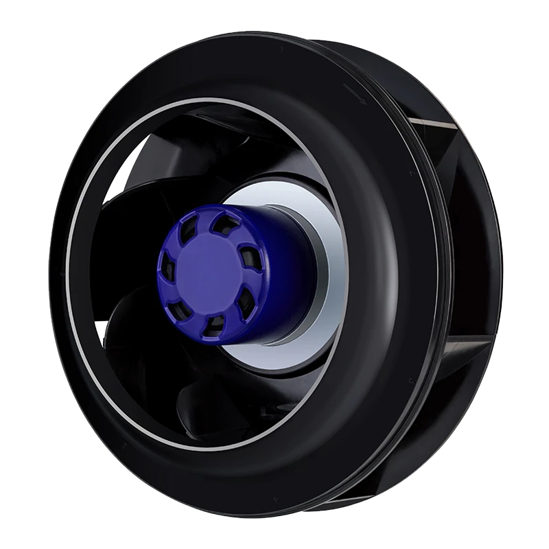
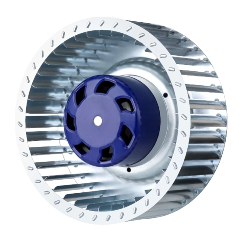
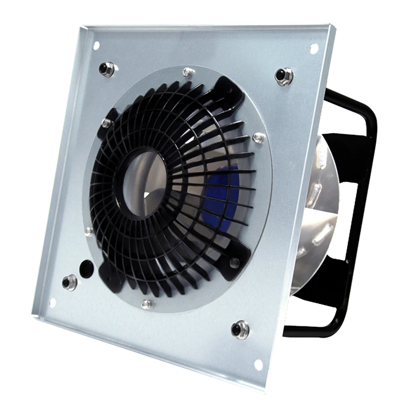
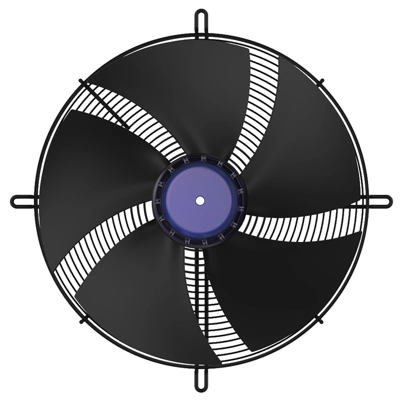
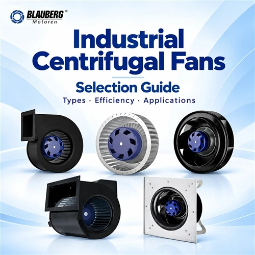
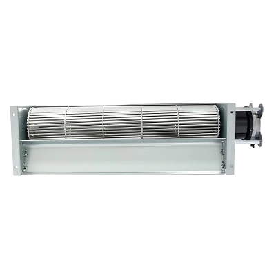
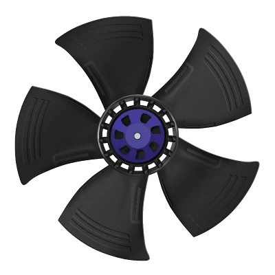
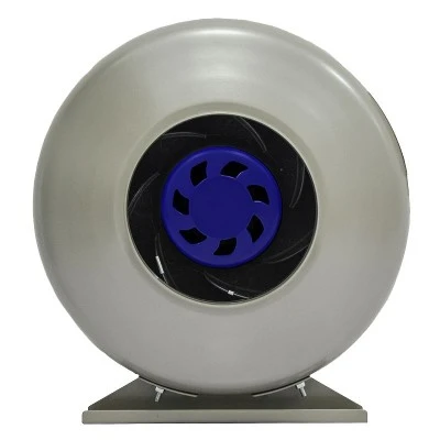
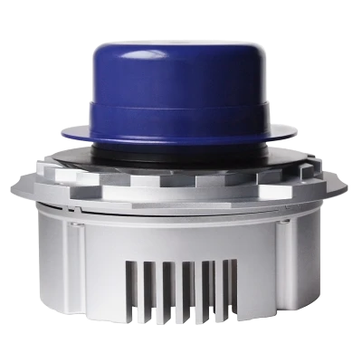
Five Blauberg centrifugal product configurations, arranged from left to right in the same order as the comparison below. Based on company-supplied product artwork; this overview does not assign model-specific performance ratings. Explore centrifugal fan products ↗
What are the different types of centrifugal fans shown here?
The illustration shows five Blauberg product configurations: single-inlet centrifugal blowers, forward-curved centrifugal fans, backward-curved centrifugal fans, dual-inlet centrifugal blowers and plug fans. All move air through a rotating centrifugal impeller, but their names describe different features. Understanding those features helps an OEM compare the right components before checking individual model curves.
Single-inlet and dual-inlet describe the intake arrangement; forward-curved and backward-curved describe blade curvature relative to rotation; plug fan describes an installation configuration. These descriptions can overlap. For example, a plug fan can have a backward-curved impeller and an EC motor. The five products illustrate useful catalogue families, rather than five mutually exclusive blade designs or every centrifugal fan type available.
01 · Single-inlet centrifugal blowers
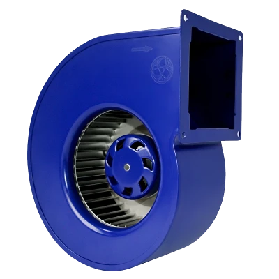
A single-inlet centrifugal blower admits air from one side of the impeller. The pictured scroll housing collects the radial discharge and directs it toward an outlet connection. For an OEM cabinet or ventilation assembly, check the intake clearance, discharge orientation and connection geometry. Select the complete wheel-and-housing combination from its documented curve; a bare impeller rating does not describe the assembled blower.
02 · Forward-curved centrifugal fans
A forward-curved centrifugal fan has blades that curve in the direction of rotation. The illustration shows the impeller and motor assembly, making the closely spaced blades visible. Housing geometry and the intended operating range matter when integrating this configuration. Check input power and motor loading as system resistance changes, especially when comparing clean and loaded filters. Appearance alone cannot establish its airflow, pressure or acoustic performance.
03 · Backward-curved centrifugal fans
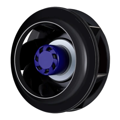
A backward-curved centrifugal fan has blades that curve away from the direction of rotation. In HVAC equipment, filtered ventilation and machinery cooling, compare candidate models at the required duty point. Review the fan curve, input power and permitted operating range together. The black wheel shown identifies a configuration; its color and blade appearance do not prove an efficiency rating or suitability for a particular environment.
04 · Dual-inlet centrifugal blowers
A dual-inlet centrifugal blower, also called a double-inlet centrifugal blower, admits air from both sides of the impeller assembly. Allow space for both intake paths and check whether nearby panels, filters or wiring obstruct either side. Use the curve for the actual assembled unit. Two inlets do not establish twice the airflow of a single-inlet model: wheel dimensions, speed, housing and operating pressure also affect the result.
05 · Plug fans
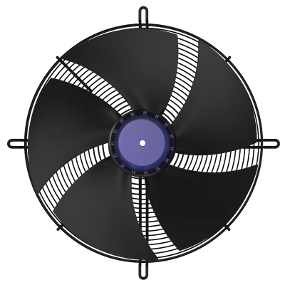
A plug fan integrates into the equipment enclosure or plenum, typically without an individual scroll housing. The pictured square mounting plate and support arrangement illustrate the mechanical interface. For air handling units and CRAC equipment, review inlet clearance, plenum geometry, removal access and controls. Where an EC plug fan is selected, confirm its supply and control interfaces from the exact model documentation; the term "plug fan" alone does not specify the motor technology.
| Configuration | Useful comparison question | What to verify |
|---|---|---|
| 01 · Single-inlet centrifugal blower | Can air reach the intake and leave through the intended outlet? | One-sided inlet clearance, outlet orientation and the complete blower curve. |
| 02 · Forward-curved centrifugal fan | Does the impeller-and-housing combination meet the full operating range? | Housing geometry, input power and motor loading as resistance changes. |
| 03 · Backward-curved centrifugal fan | Does it meet the required airflow and pressure with suitable input power? | Duty-point efficiency, inlet geometry and the permitted operating range. |
| 04 · Dual-inlet centrifugal blower | Are both intake paths available within the cabinet? | Clearance on both sides, obstructions and the assembled unit's performance. |
| 05 · Plug fan | Can the equipment plenum and mounting arrangement support the duty? | Plenum layout, mechanical fit, service access and model-specific controls. |
Explore Blauberg's single-inlet centrifugal blowers, forward centrifugal fans, backward centrifugal fans, dual-inlet centrifugal blowers and EC plug fans. Use these families to shortlist products, then complete centrifugal fan selection using matching airflow, pressure, electrical and installation requirements.
Which centrifugal fan models should you review?


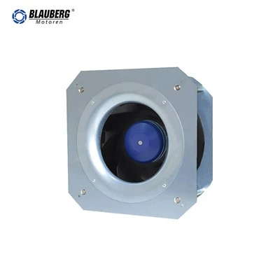
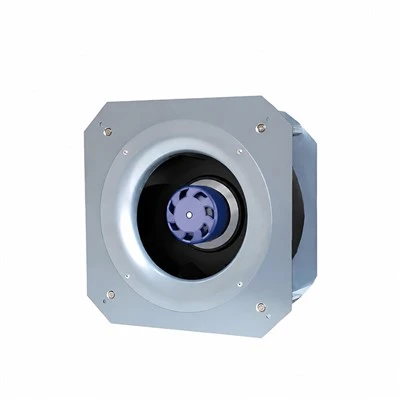


Product descriptions from the Blauberg centrifugal fan catalogue. Confirm the selected model at your operating point before release.
What information makes centrifugal fan selection reliable?
Begin with an operating requirement that the equipment team can verify. Specify airflow in m³/h or CFM and pressure in Pa or inches of water gauge. State whether the pressure requirement is static or total pressure, and identify where it applies. A pressure value without a defined boundary can lead to comparing unlike catalogue curves.
Include the actual air path: inlet grille, filter, heat exchanger, silencers, duct transitions, dampers and discharge. Record both clean-filter and end-of-service filter conditions when these affect the duty. For variable operation, define the normal point, minimum point and maximum required point instead of selecting around one exceptional condition.
Next, record air temperature, altitude or design density, moisture exposure, contamination and installation orientation. Add available voltage, phase and frequency. For an EC centrifugal fan, specify the control input and required feedback, including what should happen if communication is lost. These details belong in the initial RFQ because they can eliminate otherwise plausible models.
Finally, define the space envelope and service requirements. Include inlet access, mounting points, cable routing, removal clearance and allowable mass. A fan that fits inside the cabinet may still be impossible to inspect or replace. Treat maintenance access as part of centrifugal fan selection rather than a late installation adjustment.
How do you approach centrifugal fan sizing?
Centrifugal fan sizing starts at the intersection of the fan curve and the system resistance curve. Maximum airflow and maximum pressure are normally different ends of a performance envelope. Combining them into one supposed duty point produces a specification that the fan may never deliver.
As an illustrative requirement, consider an OEM assembly needing 3,000 m³/h at 500 Pa. Convert airflow to 0.833 m³/s before calculating air power. At that defined pressure basis, airflow multiplied by pressure gives approximately 417 W of air power. If the assumed overall efficiency on the same basis is 60%, the corresponding electrical input is approximately 694 W. These are teaching assumptions, not a rating or selection of a Blauberg model.
3,000 ÷ 3,600 = 0.833 m³/s
Air power = 0.833 × 500 ≈ 417 W
Electrical input = 417 ÷ 0.60 ≈ 694 W
The calculation helps check whether an input-power estimate is plausible, but it cannot choose the impeller diameter or establish motor suitability. Obtain a model curve at the relevant speed and air conditions. Review the power curve and the manufacturer's permissible operating region, then check what happens as resistance changes.

Manufacturer-published performance graph for GK-B400E-EC-05. Total pressure PT in Pa; airflow Q in m3/h. Model and operating conditions must be confirmed against the current specification. View source and current specification ↗
The reproduced GK-B400E-EC-05 graph is labeled PT, indicating total pressure. It should not be compared directly with a static-pressure requirement without a consistent conversion and test boundary. The displayed graph also does not replace the complete specification: confirm speed, density and installation conditions with the supplier before using it for selection.
How should centrifugal fan efficiency be evaluated?
Useful centrifugal fan efficiency comparisons hold delivered airflow, pressure basis and operating conditions constant. A motor efficiency value alone does not describe the losses of the impeller, controller and installed air path. Likewise, a lower wattage reading means little if the fan is delivering less air than the equipment requires.
For equipment that spends substantial time below maximum demand, compare several operating points and their annual hours. A transparent energy estimate adds electrical input in kW multiplied by hours at each point. Keep auxiliary loads and control assumptions consistent when comparing alternatives, and use the local electricity tariff only after the energy calculation is complete.
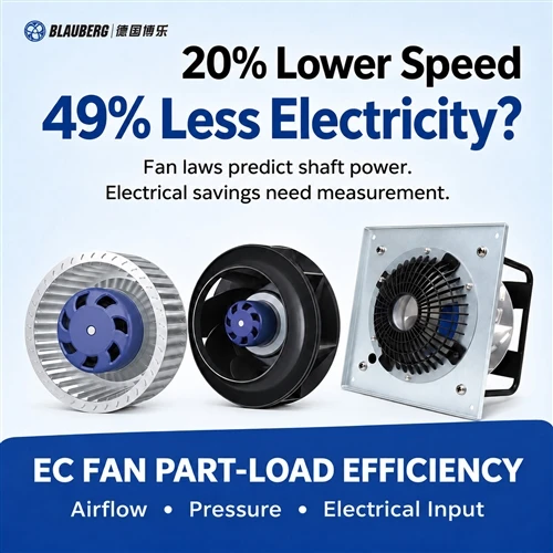
The fan laws provide a useful preliminary check for the same fan at unchanged density and comparable conditions: airflow varies approximately with speed, pressure with speed squared and shaft power with speed cubed. At 80% speed, the idealized shaft-power ratio is 0.8³, or 51.2%. This is not a promised electrical saving. Fixed pressure requirements, control losses and changing efficiency can alter the actual result.
For an energy-efficient centrifugal fan project, request input-power data at the operating points that matter. Compare a backward-curved EC centrifugal fan with the existing solution using the same duty and installation boundary. The U.S. Department of Energy fan-system sourcebook provides background on system-based efficiency improvement and speed control.
Why does installation change centrifugal fan performance?
A tight elbow near the inlet, an obstructed intake or an abrupt outlet transition can disturb flow entering or leaving the fan. The installed assembly may therefore deliver less airflow than a laboratory arrangement suggests. AMCA describes these losses as system effect and discusses how unfavorable inlet and outlet conditions increase the burden on the fan.
Review the cabinet drawing before finalizing a centrifugal fan design. Check nearby walls, structural rails, filters and wiring bundles. Preserve the clearances specified for the selected model, and evaluate the actual plenum arrangement. There is no universal clearance dimension that fits every impeller, housing and installation.

Manufacturer-published GK-B400E-EC-05 dimensional drawing, reproduced without removing its dimension labels. Verify the current drawing revision before integration. View source and current specification ↗
A dimensional drawing answers mounting and envelope questions. It does not establish aerodynamic clearance or prove that the equipment will meet an acoustic target. Prototype testing should use the production inlet, outlet, guards and filters. If a layout change is made to solve a packaging problem, recheck airflow, input power and sound together.
For background on these effects, see AMCA's system-effect guidance. It supports the installation method discussed here and is not a certification claim for the illustrated fan.
Which centrifugal fan applications fit OEM equipment?
The strongest application match begins with a known air path and a measurable duty. Blauberg's catalogue and application pages provide routes into HVAC, air conditioning, electronics and equipment cooling. Each project still needs a model-specific check of airflow, pressure, environment and electrical integration.
Air handling units and HVAC ventilation
Centrifugal fans for air handling units must overcome the combined resistance of filters, coils and connected ductwork. For an EC plug fan for AHU integration, define the required pressure at the unit boundary and identify which internal losses are included. A fan-wall retrofit also needs space, isolation, controls and service planning. Retain clean and loaded filter cases in the comparison.
Data center cooling and CRAC equipment
Data center cooling fans operate within a larger thermal and airflow strategy. Specify normal operation, reduced load and the required response to a fan outage. Several fans in parallel do not automatically establish redundancy: the remaining fans, available speed range and control sequence must support the agreed requirement. For CRAC unit fans, coordinate the coil, enclosure and delivery path before approving a selection.
Air purification and filtered ventilation
A centrifugal blower for air purification must deliver the required flow against the selected filter resistance. Define replacement criteria, monitor the relevant operating variables and provide access for cleaning. For FFU or laboratory-related equipment, the fan is only one component. Any cleanliness, containment or whole-unit performance requirement needs evidence for the complete assembly.
Machinery and enclosure cooling
An industrial cooling fan may move air through heat sinks, heat exchangers or cabinet passages. Establish the heat load, allowable temperatures and worst operating environment before translating the requirement into fan airflow. Dust, condensation and recirculation deserve specific attention. Do not infer suitability for corrosive gases, explosive atmospheres or hot process exhaust from the general word "industrial."
How can you compare centrifugal fan noise fairly?
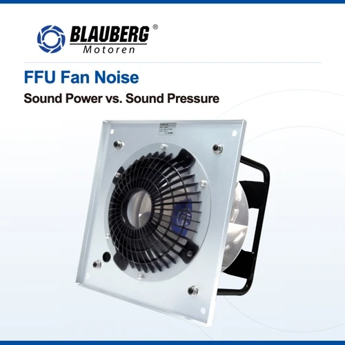
Compare centrifugal fan noise at the required airflow and pressure, with the same installation and measurement method. Sound power and sound pressure are different quantities. A sound-pressure result depends on distance, room characteristics and microphone position; a single dB(A) value without those details is insufficient for a fair comparison.
For a low-noise centrifugal fan project, define whether the target concerns inlet sound, outlet sound, casing radiation or noise in the occupied space. Ask for frequency-band information when tonal noise or an acoustic treatment is important. A quieter fan at free delivery may not remain quieter behind the production filter and outlet.
Before increasing speed to recover missing airflow, inspect the inlet and discharge arrangement. Flow disturbance, loose panels and structure-borne vibration can contribute to the complaint. Record the configuration, speed command and operating point during the noise test so that a future production change can be compared with the accepted sample.
When do inline, roof-exhaust and restoration searches need a different specification?
Centrifugal inline fans are assembled to work within a duct path. Check the complete unit's connection sizes, installed performance, mounting and service access. Blauberg's inline duct fan category is a useful starting point, but confirm the exact impeller technology and model rather than assuming every inline product is centrifugal.
Centrifugal roof exhaust fans describe a roof-mounted exhaust assembly. The specification must address the housing, roof interface, weather exposure and discharge arrangement as well as the fan component. A bare centrifugal impeller or plug fan is not automatically a complete roof-exhaust product. Confirm the assembly supplier and the intended exhaust duty before placing an order.
Questions about high-amperage centrifugal fans' limitations in water damage restoration concern a different system. Electrical current alone does not establish useful surface airflow or drying performance. A restoration equipment comparison needs the actual operating input, available power supply, placement and the moisture-removal strategy. Increasing amperage is not a substitute for verifying the intended result.
Similarly, high-amperage centrifugal fans' limitations in structural drying cannot be resolved from an OEM component catalogue. Air movement is one part of the process, and a standard ventilation fan should not be presented as a certified restoration unit without the necessary product evidence. These distinctions help buyers request the correct equipment instead of choosing from an unrelated fan category.
A location-specific search such as "industrial centrifugal fans New Jersey" adds a service requirement to the technical specification. Buyers should confirm delivery coverage, commissioning responsibility, replacement availability and local support. Such a search does not establish that a manufacturer has a New Jersey office, warehouse or installation team.
What belongs in centrifugal fan maintenance planning?
Centrifugal fan maintenance begins with the selected model's instructions and the condition of the complete assembly. Provide safe access and follow the equipment's isolation procedure before inspection. Record the fan model, electrical configuration and control revision so replacement work does not introduce an incompatible component.
Inspect the inlet, impeller and surrounding air path for contamination or obstructions using the approved maintenance method. Check mounting integrity, guards, cables and connectors. Listen for changes in sound and investigate vibration, repeated faults or reduced airflow. Service intervals should reflect operating hours and contamination exposure instead of an arbitrary schedule copied between applications.
An EC motor arrangement may avoid brush replacement and a direct-drive assembly may avoid belt maintenance, but filters and air passages still require attention. Do not treat a general "maintenance-free" motor description as a promise that the whole ventilation system needs no inspection.
What should you send when requesting a Blauberg fan recommendation?
Send a concise duty sheet and the assembly drawing with the enquiry. Identify whether you need a fan component, a blower with a housing or a complete ventilation unit. This makes the difference between comparing catalogue families and making a useful model recommendation.
| RFQ input | Include |
|---|---|
| Duty points | Airflow, static or total pressure, units, density and operating cases. |
| Electrical supply | Voltage, phase, frequency and any supply constraints. |
| Integration | Space envelope, inlet and outlet layout, mounting and service clearance. |
| Controls | Speed command, monitoring, alarm requirements and failure response. |
| Environment | Temperature, humidity, condensation, dust and conveyed-air description. |
| Acceptance | Power and acoustic limits, measurement method and sample-test conditions. |
As one documented example, the GK-B400E-EC-05 product page lists a 400 mm EC plug fan with a 230 VAC three-phase supply and 0–10 VDC or PWM speed control. It also lists RS485 communication and tachometer feedback. These details apply to that model; verify the current specification, control protocol and wiring before integration.

Manufacturer-published GK-B400E-EC-05 wiring reference. Use the current model-specific electrical instructions for installation. View source and current specification ↗
Request the current performance curve, dimensional drawing and electrical document for every shortlisted model. Keep the exact suffix and document revision on the purchase specification. A family name alone cannot establish interchangeable mounting, supply or control behavior.
How do you validate the shortlisted fan before production?
Build the sample with the intended enclosure, filter, guards and outlet components. Identify the fan and controller revisions on the test record, then define the acceptance conditions before taking measurements. The objective is to show that the proposed assembly meets a repeatable requirement, with enough information for another engineer to reproduce the comparison.
Record airflow, pressure, electrical input and the relevant temperature observations at normal demand and at the specified limiting cases. Include acoustic measurements under the agreed method. Keep clean-filter and loaded-filter results separate, and distinguish measured values from estimates. A blank measurement should remain blank until the test is completed.
Check control behavior as well as steady operation. Verify the expected response to the minimum command, changes in demand and any specified loss-of-signal condition. For fan arrays, document the agreed outage scenario and the behavior of the remaining fans. Avoid treating a successful individual-fan test as evidence that the complete array will satisfy every operating case.
Resolve discrepancies by checking measurement setup, system resistance, air leakage and control settings against the approved configuration. Keep a record of each corrective change. Once the assembly meets its acceptance criteria, retain the tested bill of materials, settings and drawings as the production reference. This connects the original centrifugal fan selection to a configuration that purchasing, manufacturing and service teams can identify.
Frequently asked questions
Is a larger centrifugal fan always more efficient?
No. Efficiency depends on where the fan operates and on the complete configuration. Compare candidate sizes at the same airflow and pressure, including control range, installation losses and available space.
Can I replace an AC centrifugal fan with an EC version?
Potentially, after checking the duty curve, supply, dimensions and control requirements. Match the complete installation and validate the replacement assembly. The label "EC" does not establish drop-in compatibility.
Can the catalogue's maximum airflow be used for a filtered unit?
Only if the corresponding pressure and configuration satisfy the unit requirement. Use a curve that includes the relevant resistance and confirm the assembled result with the intended filter and enclosure.
What is the first check when installed airflow is too low?
Confirm the actual speed command, air-path condition and measurement basis. Compare these with the selected duty and installation drawing before assuming that the motor or impeller must be replaced.
How should I compare centrifugal fan suppliers?
Ask each supplier for the same duty-point evidence, drawings, controls documentation and sample acceptance conditions. Then compare delivery, support and commercial terms for the exact proposed model.
Start with your operating point
Share your airflow, pressure, voltage, available space and application with Blauberg Motoren to discuss suitable fan configurations.
Discuss your fan requirement →Sources and scope
Model documentation checked on 29 September 2026; the product-family overview was updated on 30 September 2026. The first illustration is a redesigned layout based on company-supplied product artwork. This article explains a selection method and includes an illustrative calculation. It does not report a new laboratory test or an installation case study.
- Blauberg GK-B400E-EC-05: performance graph, dimensions and wiring.
- DOE: Improving Fan System Performance: fan-system fundamentals and energy evaluation.
- AMCA: Mitigating System Effect: installation-related losses.
Category of Blauberg Products
Built on German engineering principles, focusing on precision, reliability, and long-term performance. Through efficient and scalable manufacturing, we deliver high-quality ventilation solutions with optimized cost structure, ensuring strong value for global OEM and project-based customers.