FFU procurement guide
Two dB figures on fan filter unit (FFU) quotes are not enough to rank the products. Sound power level Lw and sound pressure level Lp measured at 1 meter are different quantities. Before comparing numbers, check that the quotes use the same item tested, airflow and pressure, installation and measurement positions, frequency bands, and weighting. Then compare like with like. The purchase agreement should also specify separate acceptance requirements for the fan test, the complete FFU, and the installed room.

Figure 1 | Conceptual cleanroom FFU application scene. It does not depict a specific Blauberg product or a customer installation.
Consider two hypothetical quotes, solely as a procurement example, not a customer case. One vendor reports Lw for a backward centrifugal fan; the other provides only "Lp at 1 meter." A lower number in the second quote does not establish that its fan will be quieter once installed in an FFU. The reports may use different airflow rates, filter resistances, and mounting arrangements. They may not even measure the same level of assembly.
Why can't you compare two FFU fan noise quotes directly?
Lw and Lp describe different physical quantities, with different reference values and test conditions. Either may be A-weighted. A report that says only "dB(A)" therefore does not tell you whether the figure is sound power or sound pressure. [1]
← Scroll sideways to see the full diagram →
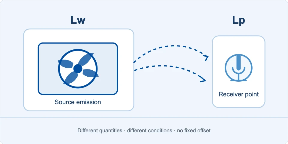
Figure 2 | Lw describes sound power emitted by a source under specified conditions; Lp describes sound pressure at a specified point. This diagram explains the distinction. It is neither a test setup nor a measured result.
← Scroll sideways to see the full table →
| Reported value | What it means | What to ask the vendor |
|---|---|---|
| Sound power level Lw | The source's sound power level under specified operating and installation conditions, referenced to 1 pW. Moving the observer does not change it; changes in airflow, pressure, speed, inlet or outlet conditions, or installation may change it. | Was the fan or the complete FFU tested? At which duty point, in which test setup, and over which sound-radiation boundary? How are bands and weighting reported? |
| Sound pressure level Lp | The sound pressure level at a specified position, referenced to 20 μPa. Distance and direction from the source, reflections, background noise, and the surrounding space all affect the reading. | From which surface is "1 meter" measured? What are the microphone direction and height, environmental conditions, and background-noise treatment? |
Converting Lw to Lp at 1 meter requires a defined sound field, installation, and measurement position. There is no universal offset. Even if both vendors quote "sound pressure at 1 meter," different positions or environments can still make the figures incomparable.
How do you compare quotes at the same duty point?
First define the air-delivery task the FFU must perform. Ask both vendors for data at that task. At each comparison point, use the same target airflow, pressure requirement, and definition of static or total pressure. Different fan designs need not run at the same speed. ISO 5801:2017/Amd 1:2025 addresses fan aerodynamic performance testing; the acoustic test method must be specified separately. [2]
← Scroll sideways to see the full diagram →
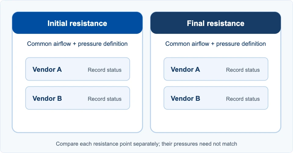
Figure 3 | Set a common comparison point for each of the initial- and final-resistance conditions. Compare the vendors at the same air-delivery task within each condition. No specific airflow, pressure, or measured result is shown.
← Scroll sideways to see the full table →
| Comparison item | What the RFQ should align | If reports differ |
|---|---|---|
| Item tested | Bare fan, fan assembly with housing, or complete FFU | List results separately; do not rank different assemblies together |
| Aerodynamic duty | Target airflow; filter and system resistance; air conditions; definition of static or total pressure | Ask for a test at the common duty point or a verifiable performance curve |
| Operating mode | Control mode and power-supply conditions; record actual speed and input power | Record how each option meets the target airflow |
| Installation and sound path | Inlet and outlet, housing, supports, and sound-radiation boundary | Align test setups where possible; otherwise document differences before comparing |
| Acoustic result | Either Lw for both, or Lp for both under specified conditions; overall level, weighting, and bands | Request results on the same basis and retain band data |
| Measurement and decision | Test-method edition, background correction, repeats, uncertainty, and pass/fail rule | Agree on these before signing so acceptance uses the same basis |
Initial and final filter resistance require separate comparison points. Compare the vendors at the initial-resistance point, then at the final-resistance point. The two points themselves do not have to share the same pressure. With constant-speed operation, rising filter resistance may reduce airflow. With constant-airflow control, speed may increase. Selecting a lower dB figure recorded after airflow has fallen does not show which fan is quieter while performing the same air-delivery task.
If a resistance element simulates the filter, identify it in the report. A simulator may not reproduce the real filter's effect on sound transmission and flow. Complete-FFU verification still needs the filter configuration specified in the contract. A backward-curved impeller does not, by itself, guarantee a noise target; duty point and installation still matter.

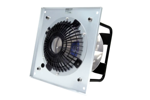
Figure 4 | Composite product application illustration. An actual product photograph is overlaid on a generated engineering workspace. This is not an on-site photograph or an actual installation case. Refer to the applicable product information and test records for the specific model, configuration, and performance.
What noise data should the RFQ request?
A single dB figure is not enough to evaluate a quote or support acceptance. Give both vendors the same data sheet. Ask them to list product configuration, aerodynamic duty, acoustic spectrum, and test boundaries, and record any differences in the bid clarification log.
- Product and duty: Identify the product and provide its airflow versus pressure curve. For both initial and final filter resistance, report actual airflow, pressure, air conditions, speed, control mode, and input power.
- Item and setup tested: Provide a configuration list for the fan or FFU, plus drawings of the inlet, outlet, filter, housing, supports, mounting, and test setup.
- Acoustic report: State whether the result is Lw or Lp. Supply unweighted band data, the contractually specified weighted overall level, test-method edition, duty point, background noise, and corrections. If reporting Lp, include a measurement-point diagram and environmental conditions.
- Spectrum and tonal character: Provide the octave-band data specified in the contract. If pure tones or prominent narrowband noise matter to the project, separately define a one-third-octave or narrowband analysis method and evaluation rule.
- Acceptance plan: Define prototype and production sampling, the number of repeated measurements, how uncertainty will be reported and used, instrument or laboratory requirements, and retesting if results are disputed.
If the parties specify AMCA 300-24, the report addresses airborne sound emitted by a fan in a specified setup. It is not a cleanroom field measurement, nor does it measure vibration or the sensitivity of sound emission to vibration. For each fan-speed condition, the standard report includes sound power data in eight full-octave bands: 63, 125, 250, 500, 1,000, 2,000, 4,000, and 8,000 Hz. The purchaser should also check reported fields such as model, airflow, pressure, speed, density, installation type, setup drawing, background noise, and corrections. The standard test process uses finer bands, but the eight reported full-octave results alone do not establish whether a pure tone is present. [3]
Testing to an AMCA method does not mean the product has AMCA certification. If certification is required, verify the applicable certification program and the product's current certified status separately. [4]
Can you compare quotes if a vendor has only a 1-meter Lp report?
Yes, if the test conditions are aligned first. Retest candidate options with the same complete-FFU configuration and common duty point, using the same test environment, measurement-point plan, and background-noise treatment. The resulting Lp values can be compared at the agreed receiving point. Lp from one position cannot be converted unconditionally into fan Lw or replace complete-unit and room-level evaluations.
At a minimum, the measurement diagram should show which surface defines "1 meter," the microphone direction and height, nearby reflective surfaces, and how other noise sources are handled. FFU inlet and outlet sound paths and mounting affect the measurement. "One meter from the unit" alone is not enough to reproduce a test. Retain the point diagram, operating conditions, and original records in the procurement file, not just the final dB figure.
How does acoustic acceptance work for the fan, complete FFU, and cleanroom?
First verify that the fan-level sound data have been delivered as contracted. Then test the assembled FFU. Once multiple units are operating in the actual room, measure the project-specified receiving points. The test object and environment change at every stage, so passing one stage does not establish that the other two pass.
← Scroll sideways to see the full diagram →
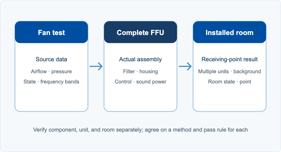
Figure 5 | The three acceptance stages are related, but the test objects and environments differ. Results cannot be converted directly from one stage to another.
← Scroll sideways to see the full table →
| Stage | What to check | What the contract must define |
|---|---|---|
| Fan test | At both common duty points, verify airflow, pressure, operating state, Lw bands, test setup, background noise, and report. | Define fan configuration, test method, and report fields. Fan-test results cannot be treated directly as FFU or room sound pressure. |
| Complete FFU | With the contracted filter, housing, mounting, and control, test airflow, external static pressure, electrical parameters, sound power, and filter-outlet airflow uniformity. | Define sample configuration, how initial and final resistance are achieved, the complete-unit test procedure, and pass/fail criteria. |
| Cleanroom field | Measure overall level and required bands at receiving points under the specified operating state; record background noise and the operating status of multiple FFUs and other equipment. | Have the project team confirm the applicable standard, room condition, measurement points, equipment operating together, target values, background treatment, and retest method. |
IEST-RP-CC036.1 covers tests of complete FFUs for airflow, electrical parameters, external static pressure, sound power, and airflow uniformity at the filter outlet. It does not set one universal pass limit for every project and is not a method for cleanroom field acceptance. [5] The project designer and owner must confirm room acoustic targets, including the applicable standard, operating state, measurement points, and target values. dB values from multiple FFUs cannot be added arithmetically; receiving-point levels also depend on frequency bands, transmission paths, room conditions, and background noise.
How do you write an enforceable acoustic purchase clause?
Put targets, test methods, required records, and decision rules in the same technical attachment. The following is a framework for an RFQ or technical agreement. The actual design values, test drawings, and mutually agreed pass criteria must be supplied in the contract attachments:
At both the initial- and final-filter-resistance conditions specified in the technical attachment, the supplier shall meet the corresponding target airflow and pressure requirements for the listed model, FFU configuration, and filter. The parties shall use the attachment's definition of static or total pressure and its mounting, inlet, and outlet boundaries. For each condition, the supplier shall submit airflow, pressure, speed, control mode, input power, and an acoustic report produced under the agreed test method and edition. The report shall include the specified Lw bands and weighted overall level. If Lp is used for comparison or acceptance, the attachment's measurement-point drawing, environmental conditions, and background-noise treatment shall govern. Prototype and production sampling, reporting and use of measurement uncertainty, retesting, and final pass/fail decisions shall follow the technical attachment. Acceptance of the complete FFU and the installed room shall follow their respective attachments.
Measurement uncertainty, variation among production units, and the tolerance allowed by the contract are different things. Whether uncertainty is deducted from a measured value must not be decided at acceptance. Before ordering, agree on the decision rule, responsibilities, and a path for disputed retests. If a supplier can provide only fan-level data, the FFU manufacturer and project team still need a verifiable plan that connects complete-unit and field acceptance.
Define the project duty before choosing a fan
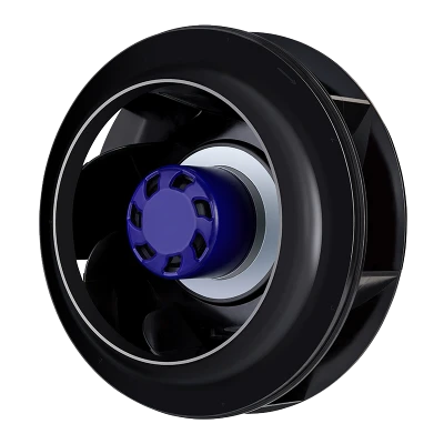
Suzhou Blauberg Motoren Technology Co., Ltd.'s backward-curved centrifugal fan range can be considered in fan-level selection. Share the target airflow, initial and final filter resistance, installation boundaries, and acoustic acceptance requirements with the supplier. Then check whether a particular model has data and test records at the relevant duty points. Its product information and actual test records remain the basis for selection.
Frequently asked questions
- Can sound power Lw be converted directly to sound pressure Lp at 1 meter?
- No fixed offset applies. Installation, measurement distance and direction, reflections, and background noise all affect Lp. A value for a specific scenario can be estimated only after the acoustic model and boundaries are defined, then checked by measurement under the agreed method.
- Does dB(A) on a report mean the value is sound pressure?
- No. A-weighting identifies a frequency weighting, not whether sound power or sound pressure was measured. The report should identify LwA or LpA, the item and operating condition tested, and the setup or measurement point.
- Must two fans run at the same speed to be compared?
- No. First require both to meet the same target airflow, pressure requirement, and pressure definition. Then record speed, input power, and control mode at each fan's resulting duty point.
- Does testing to AMCA 300-24 mean a fan is AMCA certified?
- No. AMCA 300-24 defines an acoustic test method; certification is a separate program. If the purchase specification requires certification, verify the certificate, certified product scope, and current status.
- Can a cleanroom field test be skipped if the complete FFU passes?
- A complete-unit pass does not remove the project's field acceptance requirement. With multiple units operating, the receiving point and sound-propagation environment differ from a complete-unit test. The project designer and owner must confirm room operating conditions, measurement points, and targets.
- Can the dB values of multiple FFUs be added directly?
- No. Decibels are not added as ordinary numbers. Evaluate the relevant frequency bands, combination of operating sources, transmission paths, and background conditions at each room receiving point, then verify under the agreed field measurement plan.
References
- Brüel & Kjær, Sound & Vibration Pocket Handbook, fundamentals of sound pressure, sound power, and weighting.
- ISO 5801:2017/Amd 1:2025, official record, scope of aerodynamic performance testing for fans.
- AMCA 300-24, Reverberation Room Methods of Sound Testing of Fans, Sections 2 and 9.
- AMCA Certified Ratings Program, official overview, distinguishing test methods from certification.
- IEST-RP-CC036.1, Testing Fan Filter Units, official overview; standard preview, Sections 1.1 and 1.2.
This article is a reference for comparing engineering procurement conditions. It does not guarantee the performance of any specific model or set acceptance limits for a project. Selection depends on the applicable product information and test records at the agreed duty point.