Quick Takeaways
For one or a few fans that only need continuous speed control, 0-10V is usually the most straightforward option. For multiple fans requiring status readout, parameter configuration, and fault diagnosis, consider RS485 with a supported protocol such as Modbus RTU. When there is only one temperature or pressure target, direct sensor control can be considered. For heat pumps and dry coolers, the system controller should coordinate the fans with the compressors, protection functions, and operating modes.
Start with the Control Objective
Selecting an EC axial fan starts with the required airflow at the heat exchanger resistance, then the control task. A dry cooler axial fan may regulate leaving fluid temperature, while a refrigeration condenser fan supports condensing pressure control. The same motor interface can serve either application, but the sensor location, control direction and operating limits will differ.
Treat the four options as two related decisions: how commands reach the fan, and where the control logic runs. A central controller can use either 0-10V or RS485. Direct sensor control is an arrangement that requires compatible inputs and suitable control functionality. System coordination describes responsibility for the complete machine, rather than a fourth electrical connector.
Four Control Approaches and Their Responsibilities
The interface name is only a starting point. What determines project outcomes is what is being controlled, the level of feedback detail, the safe state after a failure, and who is responsible for integrated commissioning.
|
0-10V An analog command provides straightforward wiring. Speed feedback and alarms usually require additional signals, and the actual meanings of 0V and 10V must be confirmed for the specific model. |
Basic Speed Control |
Suitable for: basic speed control, a small number of fans, and quick commissioning
|
RS485 RS485 is the physical layer, while Modbus RTU is a commonly used protocol. The project must also define addresses, baud rate, parity, the register map, byte order, and timeout behavior. |
Network Monitoring |
Suitable for: multiple fans, BMS integration, and status monitoring
|
Direct Sensor Control A compatible sensor can send an analog signal directly to the fan; confirm the regulating function as well as the electrical connection. Also check that the power supply, signal range, reference ground, control curve, and response to a broken connection are compatible. |
Local Feedback Loop |
Suitable for: a single temperature or pressure control loop
|
System Coordination The main controller calculates the fan command by considering condensing pressure, leaving water temperature, outdoor temperature, defrost status, and the number of compressor stages. |
System Control |
Suitable for: heat pumps, dry coolers, and complex operating modes
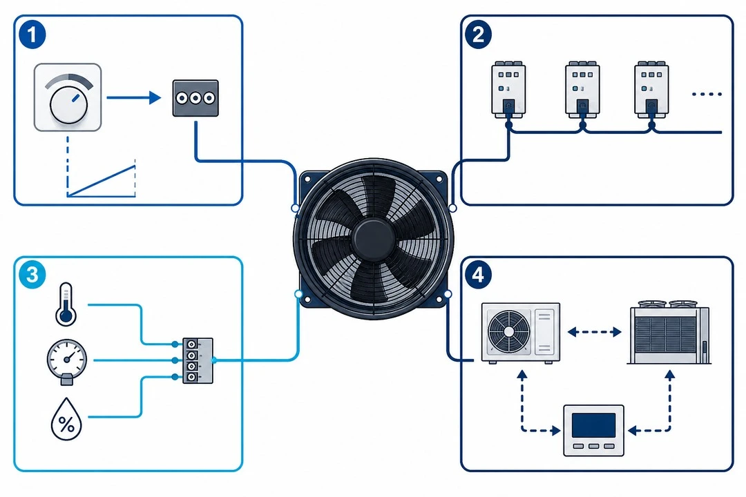
From a simple command to system coordination, control capabilities and commissioning responsibilities progressively increase
0-10V: Check the Complete Signal Path
A 0-10V EC fan is a practical choice when the equipment controller already calculates the speed demand. Confirm the input characteristic before programming the output: the start threshold, stop threshold and minimum running speed may differ between models. Do not assume that half the command voltage produces half the installed airflow. Coil resistance and the fan operating point also matter.
For several fans sharing one output, check the combined input load against the controller rating and verify the signal at the most distant fan. Confirm reference connections and cable routing in the wiring diagrams. Keep control wiring appropriately separated from power wiring. A common command gives the group a shared demand, but individual tachometer or alarm connections may still be needed to identify a failed fan.
RS485: Specify the Protocol and the Control Owner
An RS485 controlled axial fan becomes useful when the controller needs individual commands and feedback from a group. Specify the supported protocol explicitly. RS485 alone does not guarantee Modbus compatibility or a particular register set. For every required value, document its address, units, scaling, access permission and update rate. Check which diagnostic values the selected model actually exposes.
Assign a unique device address, use matching communication settings, and follow the supplier's cable and grounding instructions. The Modbus serial-line guide describes a trunk with short branches and termination at its two ends. Define polling intervals and timeout handling so that a silent device is detected without delaying the entire network.
If analog control and bus access coexist, specify which source owns the speed command and whether the bus is used only for monitoring. Verify command priority and restart behavior. Digital communication can improve diagnosis and maintenance, but savings depend on the operating strategy and equipment duty, rather than the interface name.
Direct Sensor Control: Confirm Where Regulation Happens
A sensor output connected to a speed input may simply map measured temperature or pressure to speed. Maintaining a target value requires a controller that compares the measurement with a setpoint and adjusts the command. Confirm whether that function is inside the fan, inside the sensor controller or in an external module. This distinction prevents a proportional speed response from being mistaken for setpoint regulation.
Check the sensor supply requirement, output range, input compatibility and control direction. A 4-20mA transmitter requires a compatible input or an approved conversion arrangement. A passive temperature sensor cannot be assumed compatible with a voltage input. Manufacturer control guidance illustrates these different arrangements; availability must be checked for the chosen fan.
In wind turbine inverter cooling, a local temperature loop may suit a clearly defined cooling duty, subject to the equipment requirements. Position the sensor where it represents the protected component or process. Specify what happens if its reading is missing or implausible, and verify that any higher-level protection can override normal speed regulation.
Define the Boundaries in the Technical Agreement Before Selecting an Interface
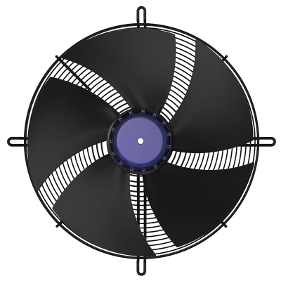
Blauberg Motoren's published Axial Flow Fans series information lists control methods including 0-10V, PWM, and RS485. Final selection must still be based on the specific part number, with the wiring diagram and protocol version checked item by item.
Specify at Least Six Items in the Technical Agreement
Fan arrangement: Quantity, grouping, duty rotation, and redundancy strategy
Feedback requirements: Actual speed, operating hours, alarms, and fault codes
Signal definition: 0-10V, 4-20mA, PWM, or a digital bus
Failure response: Safe state after a broken connection, power loss, or communication timeout
Operating limits: Minimum stable speed, startup threshold, and acceleration ramp
Division of responsibilities: Who is responsible for register mapping, integrated commissioning, and acceptance testing
How to Coordinate Fans with Heat Pumps and Dry Coolers
The controller can issue commands through an analog signal or a digital bus, but the fan demand must reflect the overall system objectives.
| Typical System | Suggested Approach |
| Basic heat pump | The main controller outputs a common 0-10V command using the relevant pressure or temperature signal for the active operating mode. Commissioning is straightforward, but visibility into individual fan status is limited. |
| Modular dry cooler | The main controller calculates the group target, while RS485 reads the status of each fan, making fault diagnosis and maintenance easier. |
Protection Cannot Rely on Communication Alone
Whether using 0-10V or Modbus, retain hardware high-pressure protection, fan fault inputs, and a safe mode for communication loss. Defrosting, frost protection, low ambient temperature operation, and coordination across multiple circuits should be handled by a controller with visibility into the overall system status.
Heat Pump Operation: Coordinate Modes and Transitions
For a heat pump outdoor unit fan, define separate control sequences for heating, cooling, startup and defrost. The outdoor coil changes duty between operating modes, so a pressure-based strategy valid in one mode cannot simply be copied into another. The main controller should select the relevant measurements, limits and command priority for the active mode.
During defrost, follow the heat pump manufacturer's approved fan sequence, including any stop, restart delay or speed ramp. Do not infer reverse-running capability from the presence of RS485. For a low noise EC axial fan, evaluate night-time limits alongside required heating or cooling capacity: a quieter speed setting is useful only if the system still meets its operating requirements.
Dry Coolers: Plan Group Control and Fault Recovery
When specifying an axial fan for dry cooler service, define the leaving fluid temperature target together with design flow, ambient conditions and coil resistance. The controller can modulate a group together or stage available fans according to the equipment design. Check the transition between stages so that added airflow does not cause repeated starts and stops around the target.
A data center dry cooler fan may form part of redundant data center cooling. Individual status feedback helps identify unavailable capacity, but extra installed fans alone do not prove redundancy. Verify the remaining cooling capacity at the specified ambient and load conditions after a fan failure. Record whether the controller raises the remaining fan commands, starts a standby group or requests a system-level load reduction.
For an EC axial fan for condenser duty, balance fan operation with the refrigeration system's pressure requirements. Evaluate total equipment power and temperature or pressure stability under representative conditions. The lowest fan speed is not automatically the lowest-energy setting for the complete machine.
Commissioning Must Go Beyond Checking Whether the Fan Spins
Acceptance testing should cover normal regulation, signal failure, individual fan faults, and low-load operation, while recording the controlled variable, command, actual speed, power, noise, and alarms together.

On-site commissioning must verify the control curve, protection functions, and takeover logic for multiple fans together
Record Results That Can Be Reproduced
Prepare an acceptance sheet with the requested setpoint, measured temperature or pressure, speed command, actual speed and alarm state. Record ambient conditions and the active equipment mode so that later checks can reproduce the same operating point. Agree the permitted deviation and settling time with the equipment designer before testing, instead of judging success only by visual observation.
Repeat representative checks after a power cycle and after restoring a lost control signal. Confirm that saved settings return correctly and that automatic operation resumes according to the agreed sequence. For procurement, request the wiring diagram, parameter file and protocol documentation alongside the performance selection. These records give maintenance staff a reference when replacing a fan or diagnosing changed behavior.
Conclusion
Selecting an EC axial fan control interface begins with the system objective, required feedback and agreed failure response. Use 0-10V when a controller needs straightforward speed modulation and separate alarm signals provide enough visibility. Choose RS485 with a confirmed protocol when individual fan commands, operating data and diagnostics justify the additional integration work. Direct sensor control suits a defined local duty only when the sensor, input and regulating function are compatible.
For heat pumps and dry coolers, assign overall responsibility to the equipment controller. It must coordinate fan demand with operating modes, compressor or pump operation, defrost requirements and protection. Establish command priority, minimum speed, ramp limits and the response to sensor or communication loss before commissioning. Multi-fan arrangements also need a verified strategy for unavailable capacity.
Complete selection with the exact part number, wiring diagram, supported register map and documented control sequence. Acceptance testing should connect command and speed measurements with the actual temperature or pressure response, then verify low-load stability, fault recovery and restart behavior. The right solution is the one that delivers the required thermal performance, manageable noise and clear maintenance information throughout the equipment's operating range, with responsibilities that the supplier, integrator and operator can all understand.