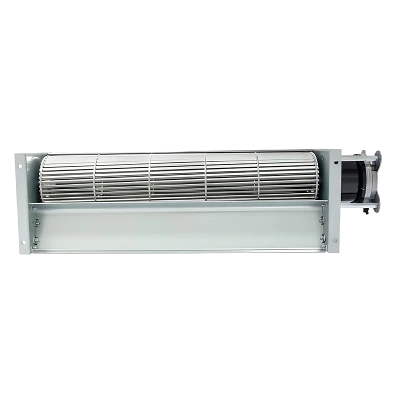
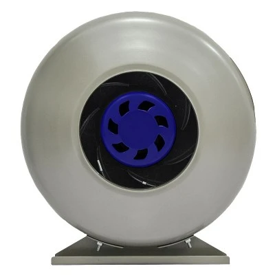
When conducting acceptance testing on a forward centrifugal fan with forward-curved blades, first fix the rotational speed, installation boundary conditions, and measurement methods, then assess the airflow–pressure curve, frequency spectrum, and vibration together. Low outlet airflow alone does not prove backflow, and increased noise cannot be attributed directly to the volute tongue. To assess consistency across production batches, prototype results must also be traced to impeller dimensions, assembly clearances, and manufacturing batches.
A prototype passes on the test bench but delivers insufficient airflow once installed in a cabinet; replacing the impeller with another of the same model changes the sound again. In such cases, adjusting the volute tongue directly is often premature. First answer two questions: Are you comparing the same operating point? Apart from the impeller, have the inlet, outlet, or mounting arrangement changed?
Installation boundary conditions vary by application, but the basic diagnostic approach remains the same: check the operating point and installation conditions before attributing a performance change to the volute tongue or outlet backflow.
01 Treat the Volute Tongue, Impeller, and Outlet as a Single System
The volute tongue is a localized feature of the volute casing near the outlet. Experimental studies of forward-curved centrifugal fans show that the shape and position of the volute tongue, as well as clearances between components such as the impeller and volute tongue, affect the aerodynamic and acoustic performance of the fans tested.
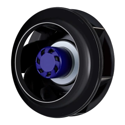
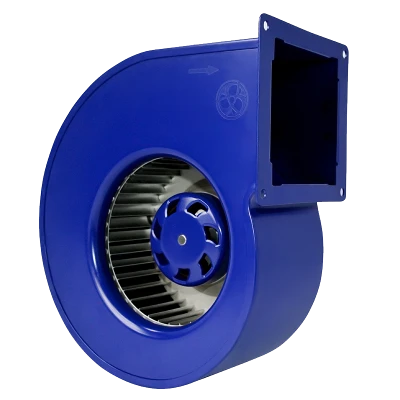
For Centrifugal Fans with a volute casing-including Forward Centrifugal Fans and enclosed Centrifugal Blowers-check the impeller, volute tongue, and outlet together to assess how their geometry and fit affect the airflow path.
Therefore, volute tongue dimensions cannot be considered in isolation from the overall fit between the impeller and volute casing. Relevant studies demonstrate interactions among these dimensions, but do not directly provide an 'optimal clearance' applicable to every fan model. For different impellers, volute configurations, and operating ranges, specific dimensions still need to be validated under actual operating conditions.
When reviewing drawings, check key dimensions together-including the volute tongue position, impeller outside diameter, axial mounting position, and inlet fit-to establish a complete dimensional chain. Also define the measurement datums for these key dimensions to avoid deviations in actual assembly dimensions caused by inconsistent datums.
For a custom forward centrifugal fan or OEM forward centrifugal fan, release the impeller, volute, inlet, and outlet interfaces under the same drawing revision. For a single inlet centrifugal blower, carry these measurement datums through design, incoming inspection, and assembly records as well.
Simply increasing one clearance without retesting fan performance at different operating points is not enough to conclude that the noise problem has been resolved.
02 Reduced Airflow Is a Clue, Not Evidence of Backflow
Once a fan is installed in a cabinet, obstructions near the inlet and outlet, nonuniform inlet airflow, and unsuitable duct connections can all cause actual operating performance to differ from laboratory test results. AMCA classifies these effects of adverse flow conditions as system effects.
For an HVAC centrifugal fan, AHU centrifugal fan, or air conditioning unit centrifugal fan, nearby coils and plenums are part of the installation conditions to review. For fresh air unit and dehumidifier fans or an air purifier centrifugal fan, filters and compact transitions can also affect the installed operating point.
Retesting forward centrifugal fans for compact HVAC equipment should therefore include the installed layout as well as the bench setup, accounting for internal cabinet partitions, nearby elbows, dampers, and guards. Apply the same verification approach to a high static pressure centrifugal fan: compare complete curves at matched speed and air conditions before attributing the change to tongue geometry.
Troubleshooting can follow this sequence: first check instrument status and speed records, then compare test results for the original installation and a controlled installation under the same operating conditions, and finally use the results to decide whether further local flow-field measurements are needed. Change only one factor at a time to identify which modification caused the performance change.
This table is intended to organize practical troubleshooting, not to serve as a standard for identifying backflow. Tests involving local flow fields should follow a measurement plan tailored to the equipment and operating conditions. Opening guards while the equipment is running to observe airflow is also not recommended.
03 Correlate Noise, Vibration, and Airflow at the Same Operating Point
Aerodynamic performance, airborne sound, and mechanical vibration tests address different aspects of fan performance. AMCA's materials on centrifugal fans list separate methods for aerodynamic and acoustic testing; the scope statement for AMCA 300 also makes clear that airborne sound testing does not include vibration measurement.
Therefore, a sound pressure value at a particular measurement location cannot be treated as sound power, and passing a dynamic balance test cannot replace vibration acceptance testing after installation. Acceptable airflow and normal-sounding operation do not automatically mean that the entire speed range has been validated.
A complete test plan should define at least the following categories of data:
-
Aerodynamic performance: airflow, pressure definition, rotational speed, air conditions, input power, and test apparatus.
-
Acoustic performance: whether sound pressure or sound power is measured, the weighting used, frequency bands, background noise, and measurement locations or test arrangement.
-
Vibration performance: measurement locations and directions, mounting stiffness, rotational speed, units, and frequency range.
-
Thermal conditions: motor temperature measurement locations, ambient temperature, temperature stabilization criteria, and whether operation remains within the product's permitted operating range.
This information needs to be defined before testing. Specific test methods and acceptance limits should also be determined according to the product and application conditions.
Finally, data obtained at different operating points or under different installation conditions cannot simply be combined into a 'before and after improvement' comparison. Changes in data are meaningful for comparison only when test conditions remain consistent.

04 Mold Consistency Requires More Than a Dynamic Balance Report
'Produced using the same mold' establishes only that the impellers share a production source; it does not directly prove consistent performance across production batches. Assessing impeller consistency also requires separate checks in three areas: dimensions, assembly, and operation.
Geometry: Focus on the Processes That Actually Determine Blade Shape
For injection-molded impellers, traceability can include the mold number, cavity, material batch, key molding parameters, and mold repair records. For stamped or assembled impellers, the corresponding dies, tooling, and joining processes should be recorded instead; the recordkeeping approach for injection molding cannot simply be applied unchanged.
The approved drawings and inspection requirements should determine which dimensions are checked, which measurement methods are used, and what deviations are permitted.
Assembly: Dimensional Compliance Must Be Followed by Consistency After Assembly
An individual impeller meeting dimensional requirements does not mean that its assembled condition will be identical to that of others. Once the impeller is installed in the volute casing, attention must also be paid to axial position, critical clearances, fastening condition, and any rubbing or interference.
If test results differ between two impellers, interchange them and retest under the same assembly conditions. This can help determine whether the problem is more likely to originate in the impeller itself or in the assembled condition. However, this retest mainly narrows the scope of troubleshooting and cannot replace formal type testing.
Operation: Assess Dynamic Balance and Complete Fan Vibration Separately
Dynamic balance reflects the rotor's own state of unbalance, while vibration of the complete fan is also affected by mounting arrangement, support stiffness, operating speed, and other factors. AMCA 204 sets out separate requirements for rotor balance and operating vibration. Test records should include the balance grade, residual unbalance, and the operating point, rotational speed, mounting arrangement, and measurement locations used during vibration testing.
A dynamic balance report therefore needs to contain more than a 'PASS'. Key data must be linked to the specific test conditions to support subsequent traceability and comparison.
Ultimately, the question is not merely 'Did this impeller pass dynamic balancing?' but whether impellers from the same batch can maintain stable, consistent performance under the same assembly and operating conditions.
05 Agree Separately on Prototype Release and Production Batch Retesting
Prototype testing primarily confirms whether the design and installation conditions meet requirements; production batch inspections aim to detect deviations in manufacturing, materials, or assembly in a timely manner. The two serve different purposes. A prototype passing its tests does not mean that subsequent production units no longer need inspection.
In practice, the following sequence can be used:
-
Freeze the drawings and test conditions
-
Complete comprehensive prototype testing
-
Confirm critical dimensions and retain samples
-
Conduct batch inspections
-
Reassess the need for validation whenever the design, materials, or processes change
The frequency of production batch retesting should be determined by project risk, production process stability, and historical deviations. Risks differ across products and applications, so a single fixed sampling rate or tolerance should not be used as a universal requirement for all fans.
06 Check These Items First When You Receive the Report
When reviewing a report from a forward centrifugal fan supplier, first confirm that it can be linked to the product actually delivered: are the model, serial or prototype number, impeller tooling or mold, drawing revision, test date, and installation arrangement fully documented? Data comparisons are meaningful only after the test item and conditions have been confirmed.
Next, check whether the test conditions are consistent: are the pressure definition, rotational speed, and air conditions the same? When conditions differ, apparent differences in curves or test results do not directly establish that product performance has changed.
Also confirm that the report covers the actual operating range rather than presenting only the best-performing operating point. For deviations or changes that have already occurred, further confirm what was changed, who approved it, which items were covered by retesting, and whether the previous revision has been segregated.
A useful test report should do more than state a 'pass' result. When a problem occurs, it should help quickly trace the relevant product, test conditions, and change records.
Conclusion: Verify the Whole System Before Adjusting One Part
Acceptance of a forward-curved centrifugal fan should start with controlled, comparable evidence. Use the duty requirements established during fan selection by airflow and static pressure to define the operating points to be verified. Fix the rotational speed, air conditions, installation boundaries, and measurement methods before comparing airflow, pressure, noise, or vibration. Reduced airflow or a new outlet tone is a clue, not proof of backflow or an incorrect volute tongue. If local backflow remains plausible after instrument, speed, inlet, outlet, cabinet, and duct conditions have been checked, use measurements that can resolve local flow direction.
The volute tongue, impeller, casing, and outlet must be evaluated as one system. A clearance change may alter aerodynamic and acoustic behavior, but its effect depends on geometry and operating point, so the complete relevant range must be retested. Production consistency also requires more than a dynamic balance pass. Link dimensions, assembly clearances, rotor balance, installed vibration, tooling condition, material or batch records, and change history to the tested unit. Prototype approval and routine batch inspection serve different purposes, and any design, material, tooling, or process change needs a documented impact review. A useful acceptance report therefore identifies the product and revision, reproduces the operating point, records the installation, compares aerodynamic, acoustic, thermal, and vibration results, and preserves the evidence needed to trace later deviations.