Tube Axial Exhaust Fan or Centrifugal Fan? An OEM Guide to Ducted Enclosure Exhaust
Compare the same duty point, verify mechanical interfaces and confirm temperature limits before prototype release.

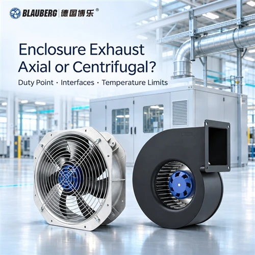
Editorial layout based on supplied axial-fan and scroll-blower images. Confirm the selected assembly against its duty, interface drawing and temperature limits.
A double-flanged tube axial exhaust fan is a candidate arrangement, not proof of suitability. Compare it with a centrifugal exhaust fan at the same airflow, pressure definition and air density, then approve the complete mechanical, thermal and electrical configuration. The selection is complete only when the installed enclosure meets the agreed airflow and temperature requirements.
Connecting an equipment enclosure's roof outlet to a site duct changes the selection problem. The fan must now work with the enclosure intake, internal obstructions, transitions, bends and discharge route. A quotation showing a large airflow number and a convenient flange can still leave the actual operating point unresolved.
This guide gives equipment OEMs, industrial ventilation engineers and purchasing teams a practical axial vs centrifugal exhaust fan review sequence. It applies to ordinary equipment heat-removal projects; the conveyed medium and any additional application requirements must be defined separately. The goal is a documented selection that can survive installation and commissioning.
The LONGWELL enquiry published on November 4, 2026 illustrates this review problem: the proposed arrangement was still under evaluation, with no final model or installed performance established. Here, that enquiry is used as topic context. It is not a Blauberg test result.
In this guide1. Map the complete enclosure-to-duct air path
Begin equipment enclosure exhaust fan selection with one coordinated layout. Show where replacement air enters, where heat is released, where air leaves the enclosure, and where the site duct finally discharges. Mark the fan's inlet and outlet planes. Include guards, screens, flexible connectors, dampers and weather terminals that will actually be fitted.
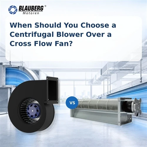
A tube axial fan normally offers an axial route through a cylindrical casing. A double-flanged arrangement can provide mechanical connections at both ends. A scroll-housed centrifugal fan takes air into the wheel axially and discharges through a differently oriented outlet. An unhoused EC plug fan instead needs an appropriate plenum or enclosure to collect and route its discharge. These arrangements require different drawings, even when their proposed duty points are identical.
For each option, identify the equipment supplier's scope and the site's scope. Who supplies the reducer? Who supports the vertical duct? Who selects the discharge terminal? Record the answer beside the relevant component. Otherwise, a duct added after factory testing can become an unrecorded change to the approved system.
Account for air entering the enclosure as carefully as air leaving it. An undersized intake opening, a loaded filter or a closed service panel can change the available flow. Also check for a short path between the intake and exhaust that bypasses the components needing cooling. Total exhaust airflow alone does not establish the temperature at every internal hot spot.
Nearby fittings matter. Uneven inlet flow and unsuitable outlet connections can make an installed fan perform differently from its laboratory rating. AMCA's system-effect guidance explains this distinction. Ask the supplier to review the proposed geometry and any required straight lengths; do not apply one universal clearance rule to every fan.
Review output: an air-path drawing with component identifiers, airflow arrows, support points, measurement stations and a clear boundary between equipment and site responsibilities.

Conceptual flow sequence; positions and dimensions must come from the coordinated equipment and duct drawings.
Product configurations to identify on the drawing

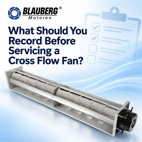
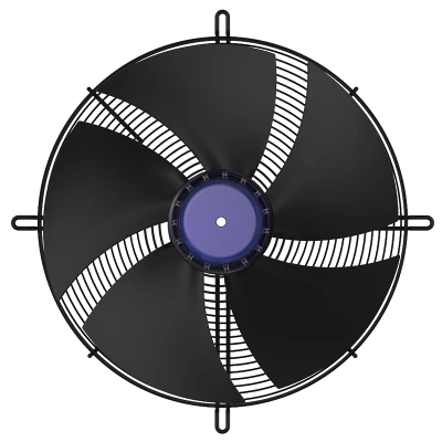
Axial fan with a guard and mounting frame. Confirm the complete duct connection and casing arrangement.

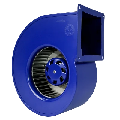
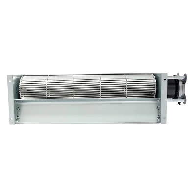
The scroll routes air to a rectangular outlet; include its orientation and transition in the layout.

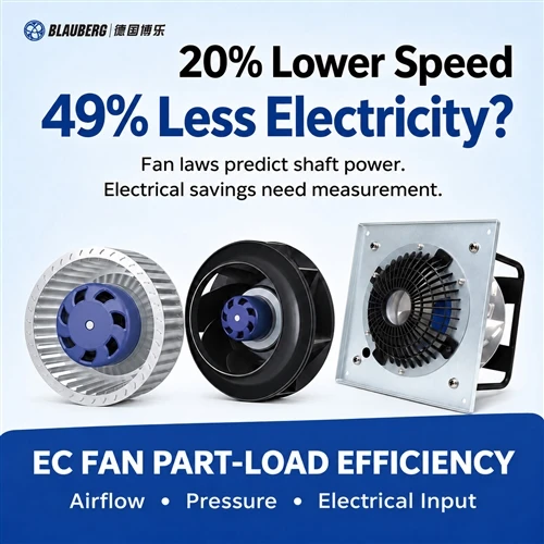
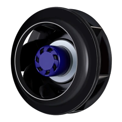
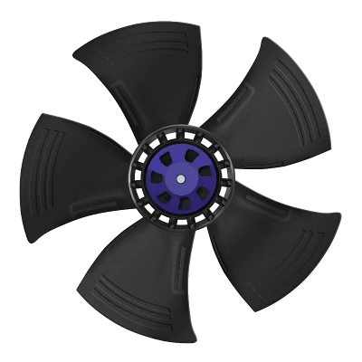
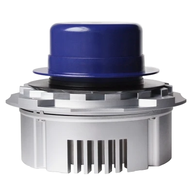
The wheel and motor are components of an assembly. Confirm the required housing and installed curve.

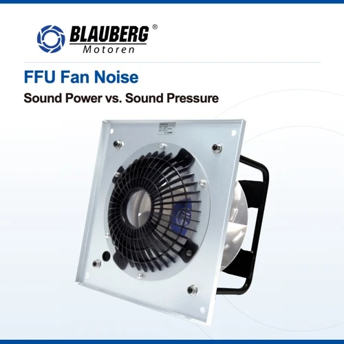
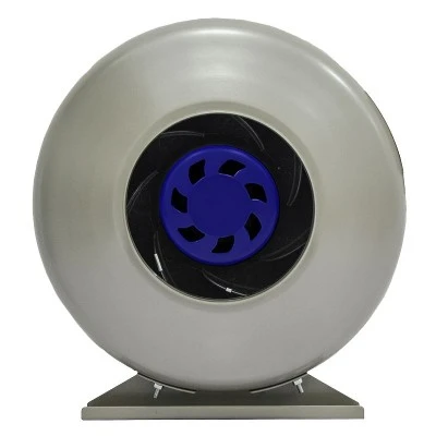
Review the mounting envelope, airflow direction and guarding for the selected installation.
User-supplied product images illustrate construction types; confirm model-specific dimensions and operating limits separately.
2. Compare axial and centrifugal fans at the same duty point
Specify airflow and pressure together. The operating point is where the installed fan characteristic and the system requirement meet on a consistent basis. Maximum airflow and maximum pressure are generally separate points on a catalogue curve. Combining them creates a duty that the fan may never deliver. AMCA's guide to fan curves shows why the curve, speed and test arrangement must accompany a selection.
Use actual volume flow at the defined air condition, or explicitly state the reference conditions if the requirement is expressed as standard volume flow. Record temperature, density and the relevant site conditions. Comparing one curve at standard density with another at the hot operating condition can conceal a pressure or power mismatch.
Identify whether the requirement is fan total pressure, fan static pressure or a pressure difference between specified duct stations. These labels are not interchangeable. In AMCA terminology, fan static pressure is fan total pressure minus outlet velocity pressure; it is not simply every possible difference between two static-pressure taps. Identify the measurement planes and conversion method in the quotation. See the pressure definitions in AMCA 803-26.
| Comparison field | Use the same basis for both proposals |
|---|---|
| Required airflow | Actual or reference volume, units and measurement location |
| Pressure requirement | Named pressure definition, boundary planes and included losses |
| Air condition | Temperature, density, altitude or barometric pressure as applicable |
| Fan configuration | Model, impeller, casing, speed, accessories and installation category |
| Operating range | Normal, minimum and maximum demand; expected resistance changes |
For a double-flanged tube axial fan duty point, request the curve for the offered assembly, including the relevant accessories. For centrifugal fan selection, identify whether the curve describes a housed blower, a free-running impeller or a tested plenum arrangement. A component curve needs an installation review before it represents the enclosure exhaust system.
Ask the design team to calculate the resistance of the complete route and document uncertainty. Review clean and expected service conditions instead of adding an unexplained percentage to every loss. If the selected point approaches an unstable region or a motor limit, obtain a revised selection. Industrial axial fans and industrial centrifugal fans should be compared through their actual characteristics, not a blanket claim that one family always wins.
A practical bid-comparison rule
Give both suppliers the same duty schedule and ask them to return a marked curve with the proposed speed, input power and configuration reference. If one proposal needs a different transition or outlet route, have the designer recalculate that arrangement's system requirement before comparing it. "Same duty" means an equivalent agreed task and consistent measurement basis; it does not mean pretending that two different duct layouts have identical losses.
Keep the normal point and the expected operating envelope visible on the same review sheet. Explain how filters, dampers, equipment doors and site operating changes were represented. Record any margin once, with its reason and owner, so that separate conservative assumptions do not accumulate unnoticed across the enclosure, duct and fan selections.

Conceptual curves for reading a duty point. No numerical scale, product rating or axial-versus-centrifugal performance advantage is implied.
3. Approve mechanical interfaces before fabrication
Do not use nominal duct size as a substitute for an interface drawing. Nominal connection diameter, flange clear opening, casing outside diameter and impeller diameter describe different features. A fan identified as a particular millimetre size may still need adapters, additional installation length or a different bolt pattern.
For both ends of a double-flanged tube axial fan, request the flange outside diameter, clear opening, pitch-circle diameter, hole count, hole diameter and angular orientation. Add flange thickness, gasket requirements and any protruding motor or terminal-box envelope. Where rectangular ductwork is involved, record width, height, corner details and the transition geometry.
For a centrifugal exhaust fan, show the inlet approach, outlet orientation, rotation reference and the connection to the site duct. Confirm whether the outlet position can be changed on the selected configuration. The drawing should include the final arrangement, rather than leaving an installer to rotate a housing or improvise a transition without review.
Use a separate removal envelope for centrifugal exhaust fan installation clearance. Can the motor, wheel or complete fan be removed without cutting the duct? Can a technician reach fasteners and connectors after insulation and adjacent equipment are installed? Leave space for the actual service operation, not only for the assembled product.
Review support and alignment with the structural designer. Record fan mass, the approved mounting orientation, lifting provisions, vibration-isolation details and permitted connection loads. Do not assume a flange can carry an unsupported site duct. Flexible connectors also need agreed support and alignment arrangements; they do not replace a structural load assessment.
A useful drawing-review exercise is to trace every interface from enclosure to discharge and assign it an owner. Mark unresolved dimensions as open items with a due date. Release sheet-metal fabrication only against a coordinated revision. This makes centrifugal fan sizing and axial fan packaging decisions traceable when a late layout change affects both fit and performance.
Which Blauberg axial and centrifugal products should you review?
Recommended starting points for component selection, subject to the required duty and temperature checks. The axial products below are not presented as verified double-flanged tube axial assemblies. Plug fans and impellers need a suitable surrounding arrangement; confirm the complete installation with the supplier.


4. Separate conveyed-air temperature from motor ambient
A single temperature figure in an enquiry is incomplete. State the temperature of the air passing through the fan and the ambient temperature around the motor, bearings and electronics. These may differ, particularly where a drive sits outside a hot airstream or where a compact external-rotor assembly occupies the flow path.
For each location, define normal operation, the maximum continuous condition, start-up conditions and any permitted short-duration excursion. Specify duration and frequency rather than calling a peak simply "occasional." Ask the supplier to confirm the exact combination of temperature, speed, supply and duty for the offered motor and fan assembly.
Temperature also belongs in the aerodynamic review. Changes in air density affect the comparison between a catalogue curve and the hot installation. The U.S. Department of Energy's fan-system sourcebook identifies air properties, airflow, pressure and system layout as selection inputs. Obtain the manufacturer's corrected selection rather than treating a density adjustment as evidence of material or motor temperature capability.
Describe the medium itself: clean air, moisture, condensation risk, dust, vapour or other contaminants. An ordinary cooling fan should not acquire a special process rating merely because its wheel is metal. Where additional service requirements apply, specify them explicitly and request evidence for the complete candidate configuration.
Match voltage, frequency, phase and supply tolerances to the actual site. Identify the motor and controller by their exact references. For an EC axial fan or EC plug fan, confirm which control and feedback functions are present on that variant, what happens when the control signal is lost, and how the equipment controller interprets a fault. Avoid inferring wiring from a similar-looking model.
Finally, check operating and storage limits separately. A storage-temperature value does not authorize continuous hot-air operation. An ambient-temperature entry, insulation class or enclosure-protection marking likewise cannot, by itself, establish the maximum conveyed-air temperature. Review output: a two-location temperature schedule linked to written supplier confirmation and the final electrical drawing.
Make the temperature schedule usable
Give each temperature entry a location identifier from the drawing, a normal value, an upper continuous value and a defined transient profile where relevant. Include the equipment heat-load condition and cooling-air intake condition used to establish it. Ask the supplier to answer against those entries individually. A response that confirms only "ambient suitable" leaves the conveyed-air boundary open and should remain an unresolved technical item.

Confirm both boundaries for the exact proposed assembly and operating conditions.

Industrial equipment cooling illustration: review the intake path, internal hot spots and exhaust route together. Confirm any ratings or operating claims in the artwork against the selected model documentation.
5. Compare power, acoustics, documents and service access
Once each candidate meets the required duty and interface conditions, compare the complete package. Request electrical input at the selected operating points and identify what the measurement includes. Motor output, fan shaft power and supply-side electrical input are different quantities. A smaller nameplate rating does not automatically mean lower energy consumption at the installed duty.
Include the planned operating schedule. A fixed-speed enclosure exhaust and a demand-controlled system may spend very different hours at each load. Compare input power over those agreed conditions, together with the cost of controls, adapters, support and commissioning. Keep predicted energy use separate from measured performance until the sample has been tested.
For acoustics, request the test method, operating point and reported quantity. Sound power describes source emission; sound pressure depends on the measurement environment and position. Compare like quantities under stated conditions, and consider inlet, outlet and casing noise where relevant. A bare "dB(A)" number without those details is not a dependable purchasing comparison.
Maintenance review should follow the actual construction. Identify cleaning access, bearing or belt service where applicable, replacement parts, connector access and the time needed to remove the fan. For centrifugal fan applications involving a plenum, include access to the surrounding chamber. For a tube axial arrangement, review how a casing section can be withdrawn from between two connected ducts.
Use a document register for the project's required approvals. Record the document identifier, issuing body, applicable scope, listed model or family, motor/controller configuration and relevant conditions. Ask the responsible project reviewer to resolve gaps. A company certificate, a component declaration and evidence covering a complete fan assembly answer different questions; none should silently stand in for another.
The LANGDI purchasing comparison, dated October 27, 2026, is a useful prompt to review packaging, controls and maintenance. This guide uses those review dimensions only. It does not adopt generalized claims about efficiency, pressure capability or service life as evidence for Blauberg products.
6. Turn the selection into a prototype release checklist
Before the sample arrives, define the acceptance plan against one configuration revision. List the approved fan and motor, enclosure build, intake openings, fittings, site-duct representation, control settings and instruments. If the factory rig cannot reproduce the final duct route, state what the factory test proves and what must be checked after installation.
Choose test conditions that represent the equipment's real operating envelope. Include normal thermal load, the defined high-load condition and relevant control states. Establish a stabilization criterion and recording interval in advance. Record the temperatures at the actual components and motor environment, rather than using elapsed time alone to declare a thermal test complete.
| Release record | Evidence to save | Acceptance basis |
|---|---|---|
| Installed airflow | Measurement method, station, instrument, air condition and uncertainty | Agreed minimum cooling flow at the specified condition |
| Pressure and speed | Tap locations, pressure definition, speed and damper positions | Approved operating range and comparison method |
| Thermal behaviour | Air, motor ambient and critical equipment temperatures over time | Confirmed limits and agreed stabilization criteria |
| Electrical input | Supply conditions, real power, current and control command | Selected configuration's limits and project requirements |
| Abnormal feedback | Command, observed response, alarm, interlock and recovery record | Approved test procedure and control sequence |
| Mechanical/service review | Installed photographs, vibration observations and removal route | Approved drawings and supplier instructions |
Plan abnormal-condition checks with the supplier and equipment team. Use approved signal simulation or diagnostic methods where appropriate. Do not improvise a blocked-rotor or over-temperature test beyond the permitted procedure. The purpose is to verify the agreed response, including loss of feedback or control signal, while maintaining the test rig's defined operating limits.
Record deviations with an owner, corrective action and re-test decision. If the site changes the duct, the fan variant changes, or the controller settings differ from the tested build, review the effect before accepting the substitution. Purchasing should release the approved configuration and document revisions together.
This sequence turns an axial vs centrifugal fan comparison into an auditable OEM decision. Select the arrangement that meets the documented duty, thermal limits, installation needs and service requirements. A convenient shape or a favourable catalogue maximum can begin the shortlist; measured installation performance closes it.
RFQ wording to adapt for your project
Please provide a selection for the attached enclosure and duct-layout revision. State the offered fan, motor, controller, accessories and installation arrangement. Mark all requested airflow-pressure duties on curves at the specified air condition and identify the pressure definition and test setup. Return the interface drawing, continuous and transient temperature confirmation, electrical connection details, control/fault sequence and applicable configuration-specific documents. Identify assumptions, exclusions and deviations explicitly. Propose the factory and installed acceptance measurements, including tolerances and uncertainty, for agreement before sample testing.
Frequently asked questions
Can a double-flanged tube axial structure alone prove suitability?
No. It establishes an intended connection arrangement. Confirm the exact assembly's duty point, installed air path, mechanical dimensions, thermal limits and electrical configuration before approving it for enclosure exhaust.
How should an axial vs centrifugal exhaust fan comparison be normalized?
Use the same airflow basis, air density and named pressure definition. Identify the measurement planes, speed, fitted accessories and installation arrangement. Request both candidates' curves on that agreed basis.
Why cannot maximum airflow and maximum static pressure form one duty point?
They describe different locations on the performance characteristic. Require the supplier to mark the requested airflow-pressure pair on the curve for the offered configuration and confirm its operating range.
Which dimensions distinguish a tube axial fan from its duct connection?
Check nominal duct size, flange clear opening, casing outside diameter and impeller diameter separately. Obtain bolt pattern, flange thickness, installation length and the motor or terminal-box envelope from the approved drawing.
Why specify air temperature and motor ambient separately?
The air being conveyed and the environment around the motor or electronics may impose different limits. Confirm continuous and transient conditions for each location, including their duration and the selected operating duty.
What changes when a centrifugal exhaust route turns the airflow?
The layout may need a different outlet position, transition, elbow and support arrangement. Review those losses together with the inlet approach and the clearance required to remove and service the fan.
How should OEMs check approval documents?
Match each required document to the exact offered model, motor, controller and assembly scope. Have the designated project reviewer resolve exclusions and configuration differences before purchasing releases the order.
What records should accompany an enclosure exhaust sample?
Save the approved build and wiring revisions, measured airflow and pressure, air conditions, temperature trends, electrical input and control/fault-response records. Include instrument information, uncertainty, deviations and the final acceptance decision.
Prepare your enclosure exhaust selection package
Share the enclosure drawing, site duct route, paired duty points, both temperature boundaries and supply/control requirements with Blauberg. Request a configuration-specific review before confirming the fan, interfaces and prototype acceptance plan.
Discuss your applicationReferences and evidence scope
Sources reviewed on November 12, 2026. Manufacturer articles supply topic context; official product pages are selection references, not proof of suitability for this enclosure.
- LONGWELL - Tube Axial Fan Selection for a Turbo Blower Enclosure Roof Exhaust - 2026-11-04. Topic context only; configuration enquiry, not a confirmed performance case.
- LANGDI - Centrifugal Fan vs Axial Fan: 9 Differences for HVAC Buyers - 2026-10-27. Purchasing review dimensions only; generalized performance claims not adopted.
- AMCA - Straightening Out Fan Curves - 2020-10-01. Paired duty points, curve notes and test arrangements.
- AMCA - Mitigating System Effect to Optimize Fan Performance and Efficiency - 2024-06-04 (web page date). Installed inlet/outlet geometry and laboratory rating differences.
- AMCA 803-26 - 2026. Definitions of fan static pressure and static pressure rise; not imposed as the project acceptance standard.
- U.S. DOE - Improving Fan System Performance: A Sourcebook for Industry - 2003. System selection inputs and electrical-input measurement boundaries.
Category of Blauberg Products
Built on German engineering principles, focusing on precision, reliability, and long-term performance. Through efficient and scalable manufacturing, we deliver high-quality ventilation solutions with optimized cost structure, ensuring strong value for global OEM and project-based customers.